SumoHardware v0.4.X
Assembly instructions
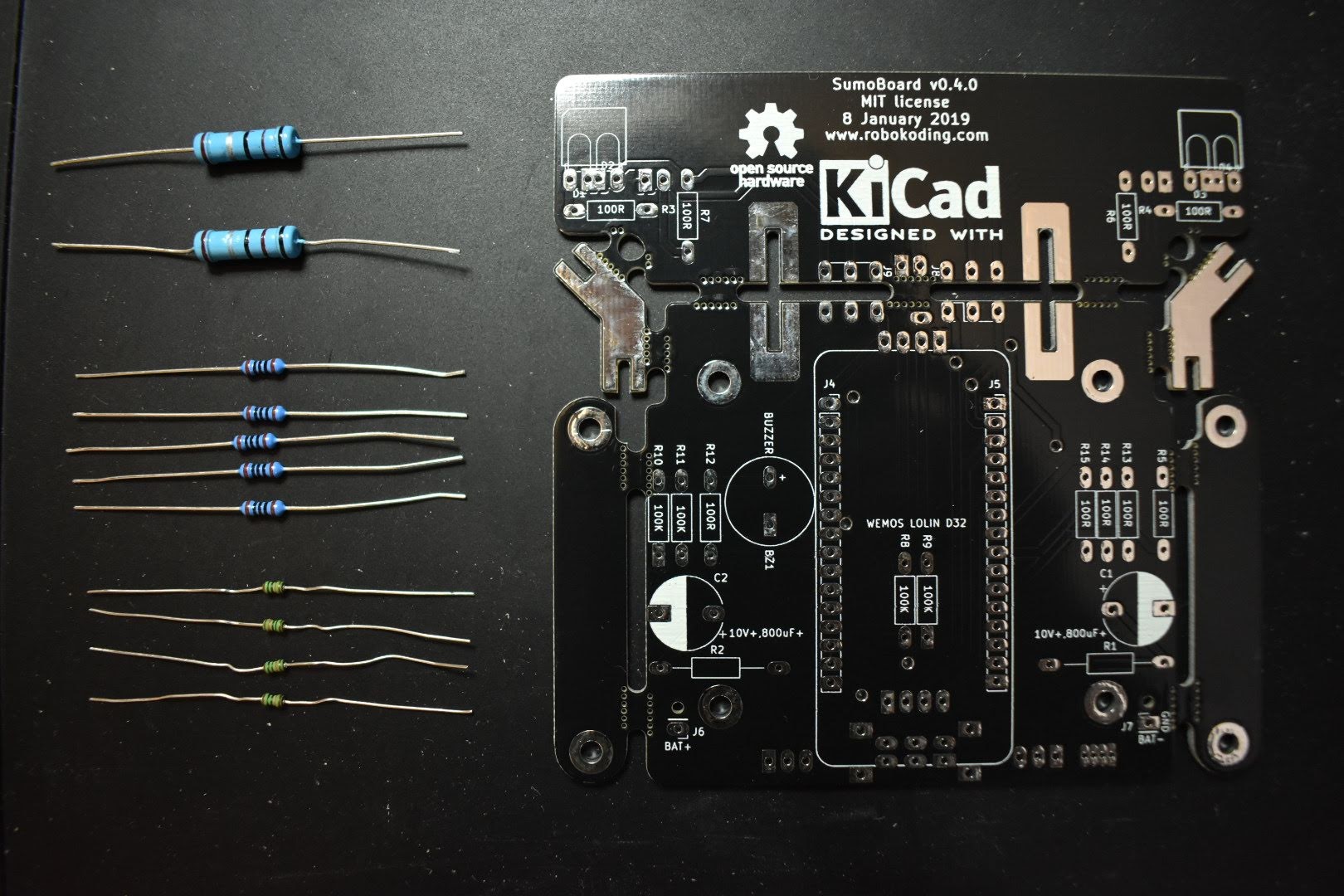
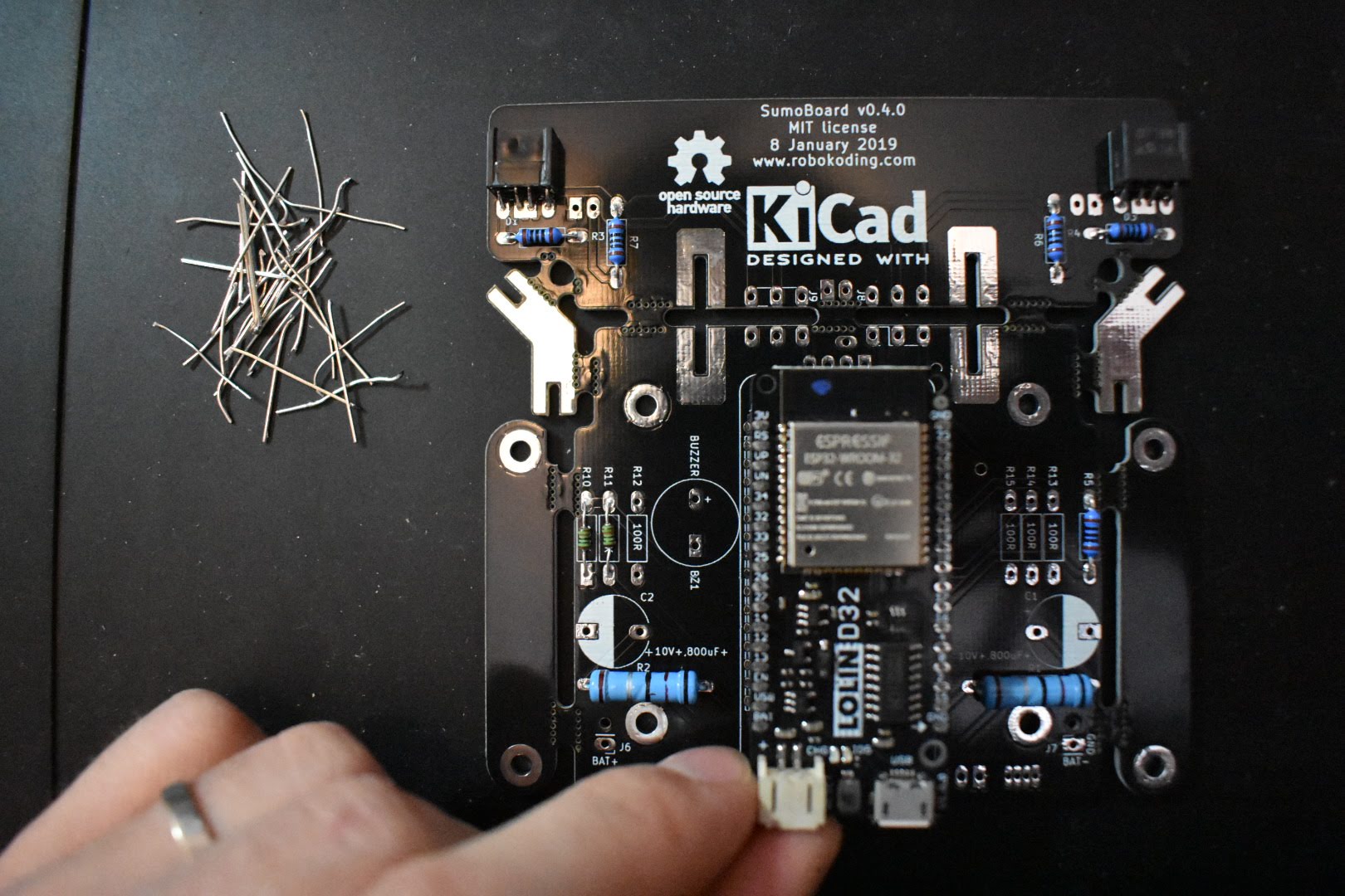
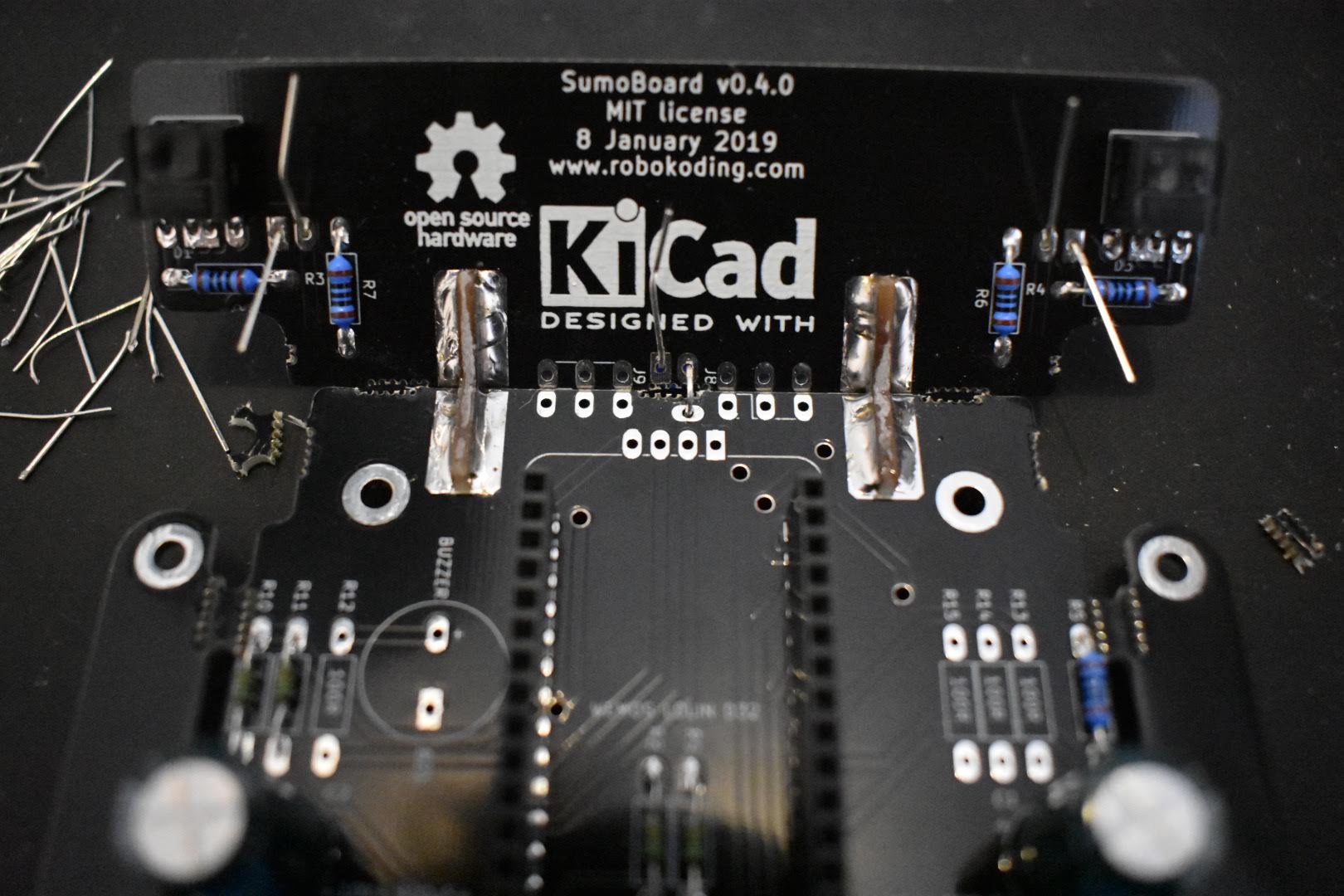
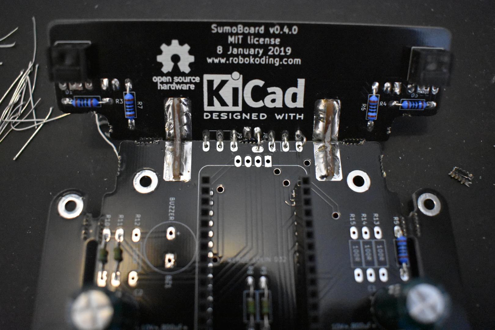
1. Solder the resistors
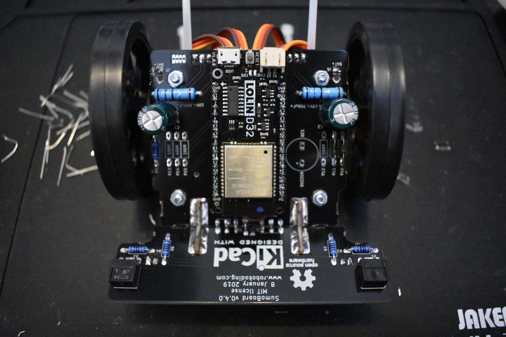
There are 11 resistors in the kit: 2 big blue, 5 medium blue and 4 small blue or green resistors - all of them with different colour codes indicating the resistance value (ohm). Flip the SumoBoard on its backside and place them according to the numbers shown below:
Big blue resistors > R1, R2 > 0.1 ohm
Medium blue resistors > R3, R4, R5, R6, R7 > 100 ohm
Small blue or green resistors > R8, R9, R10, R11 > 100K = 100 000 ohm
Bend the resistor legs 90 degrees and place them on the SumoBoard. You can place and solder them one by one, or all together. They don’t have polarity, which means that you can place them in either of the 2 orientations on the SumoBoard.
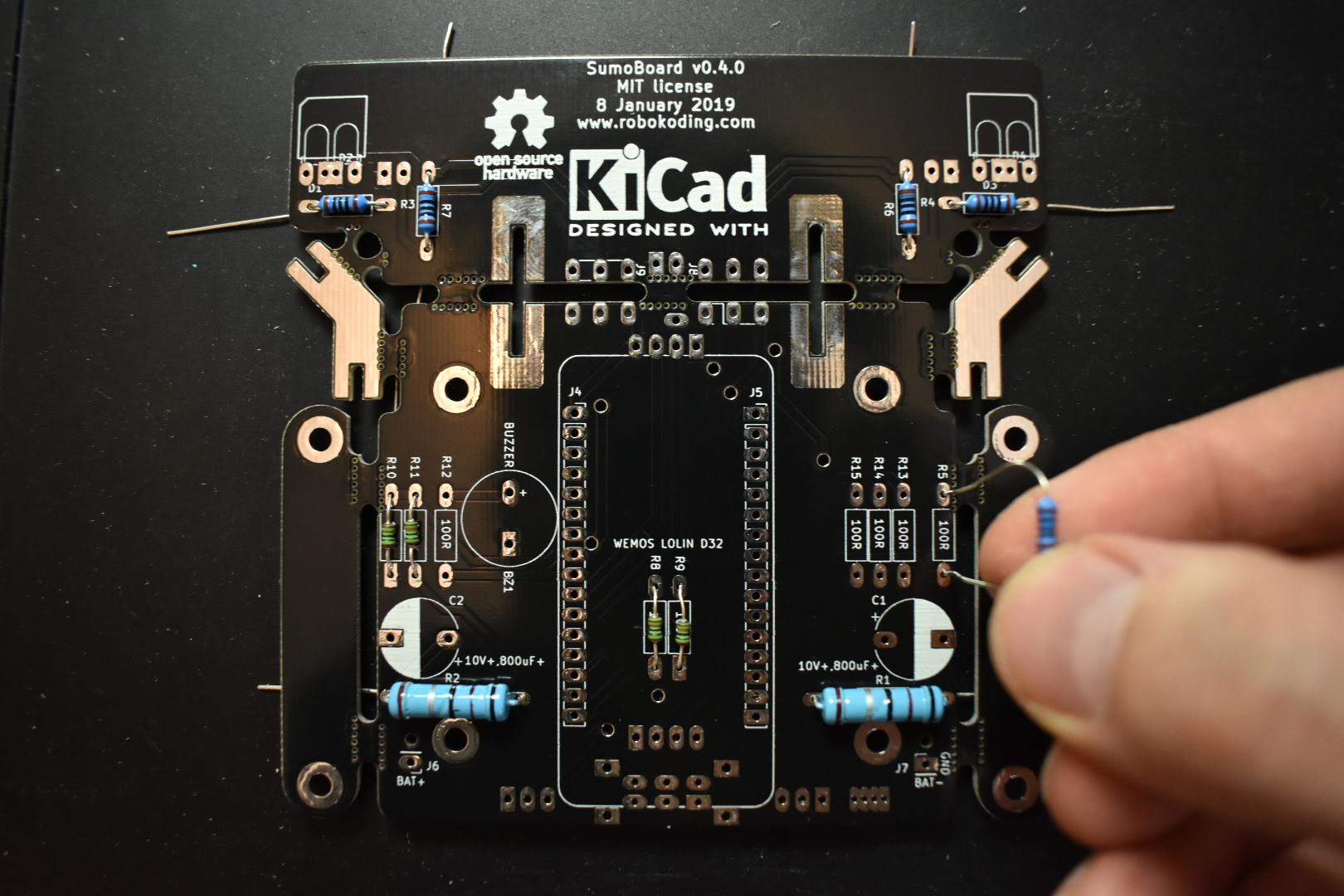
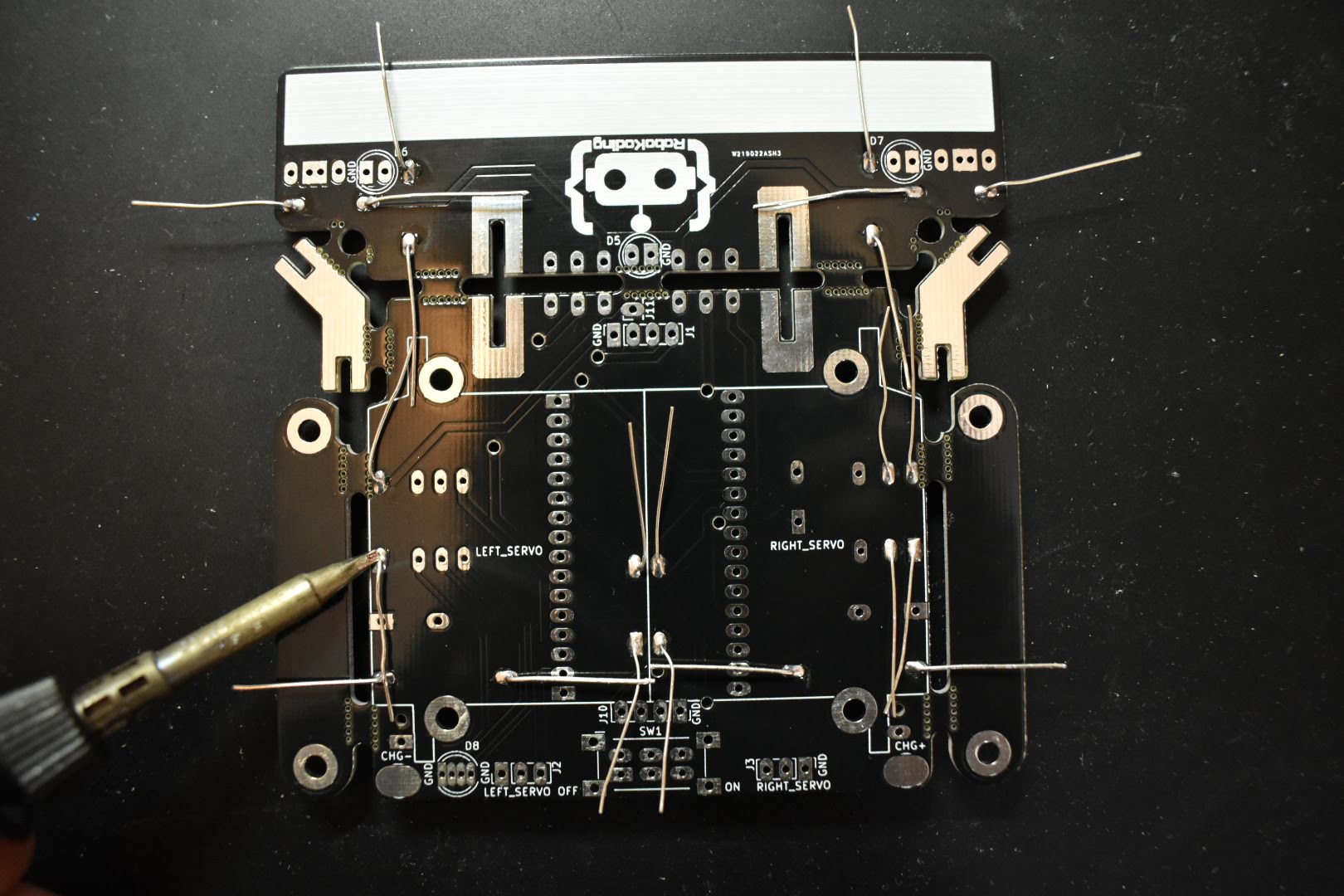
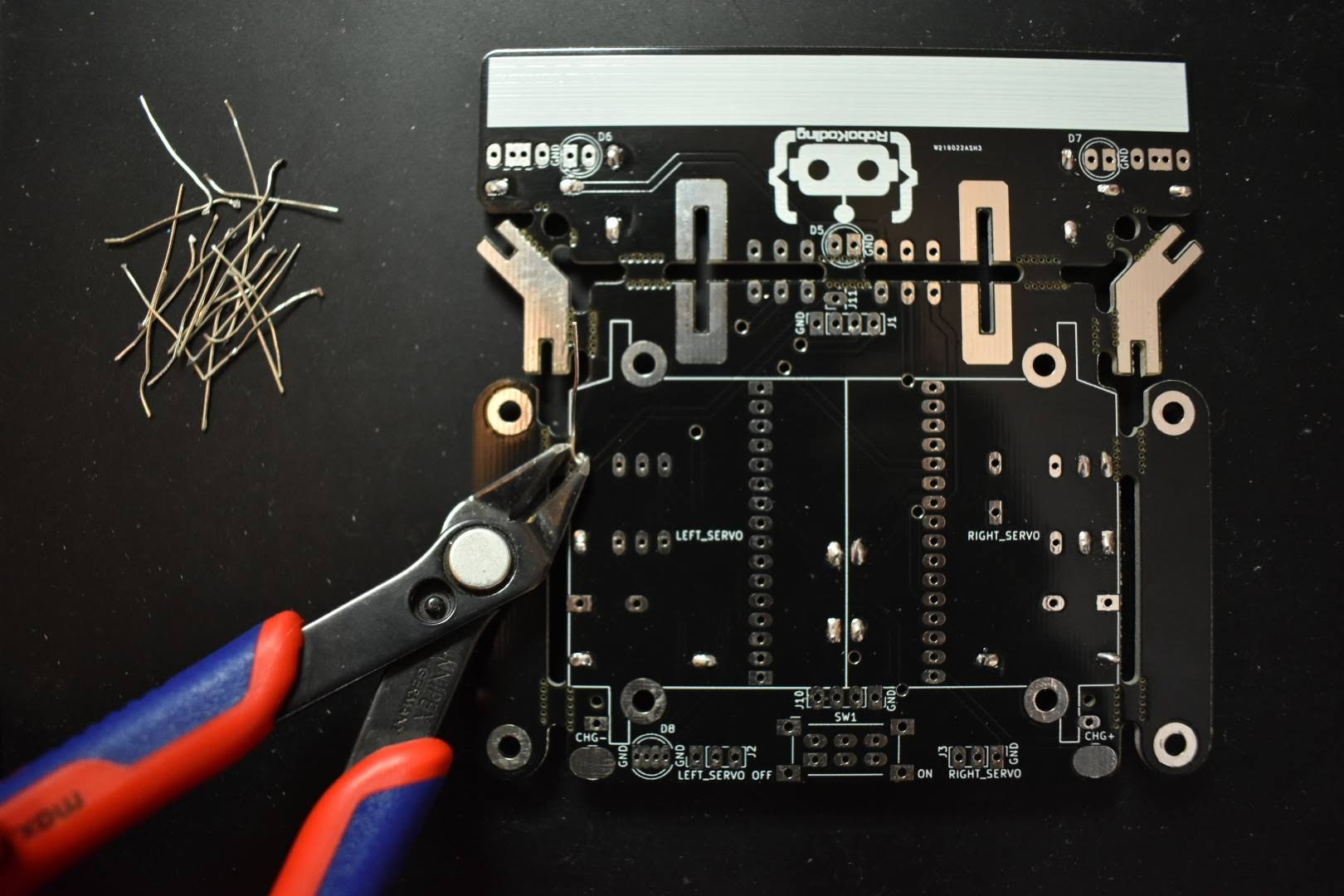
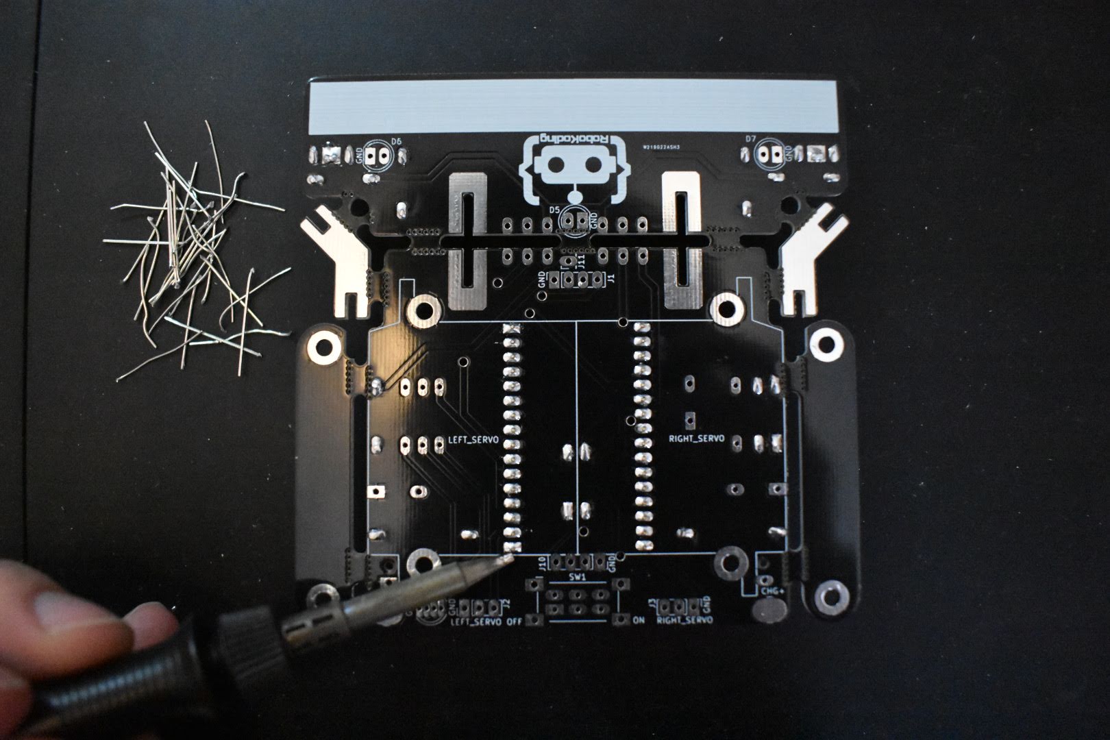
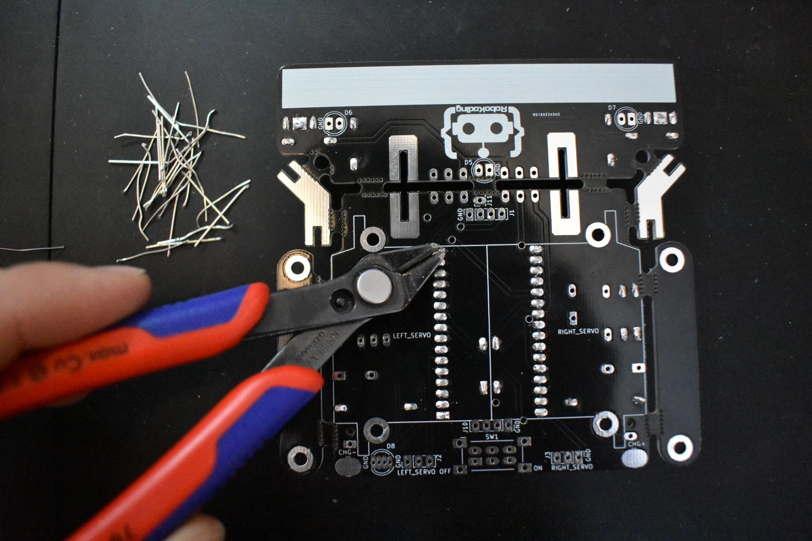
Cut the remainder of the resistor’s legs. Inside the boundaries of the right and left servo, try to cut the solder joints as flat as possible. So later the servomotors can fit on the mainboard better.
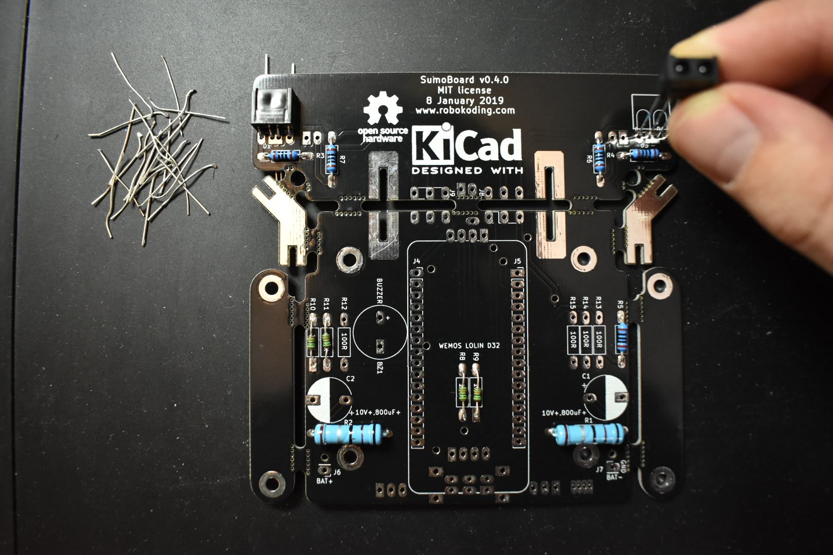
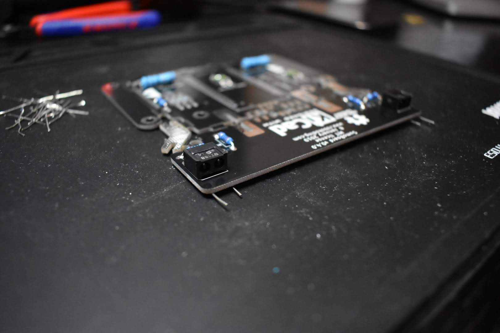
2. Solder the phototransistors
Find the two phototransistors - these are the light sensors that help the SumoRobot detect the line on the SumoRing. They are polarized, therefore pay close attention to the white drawing on the SumoBoard. The drawing corresponds to the shape of the phototransistor, therefore showing you the right way to place it on the board. One corner of the phototransistor is cut a little bit, which should match up with the drawing on the SumoBoard. Insert the phototransistors into the 4 holes (labels: D1, D2 and D3, D4) and bend their legs 90 degrees to match up with the drawing on the SumoBoard. Finally solder them into place and cut the remainder legs.
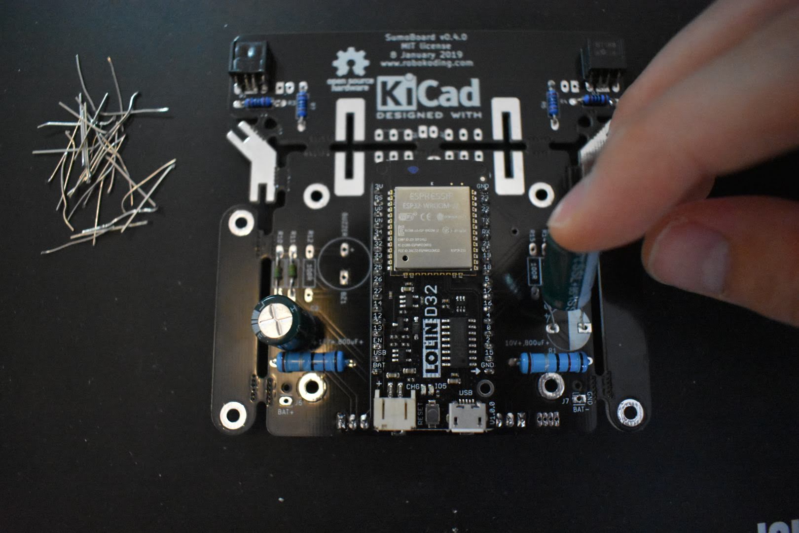
3. Solder the microcontroller
For this step you need the microcontroller, the pair of male pin headers and the pair of female pin headers. Place the female pin headers on the markings J4 and J5 on the board. Afterwards insert the male pin headers into the female pin headers and finally place the microcontroller on top of the male pin headers. Then solder the male pin headers to the microcontroller and the female pin headers to the SumoBoard.
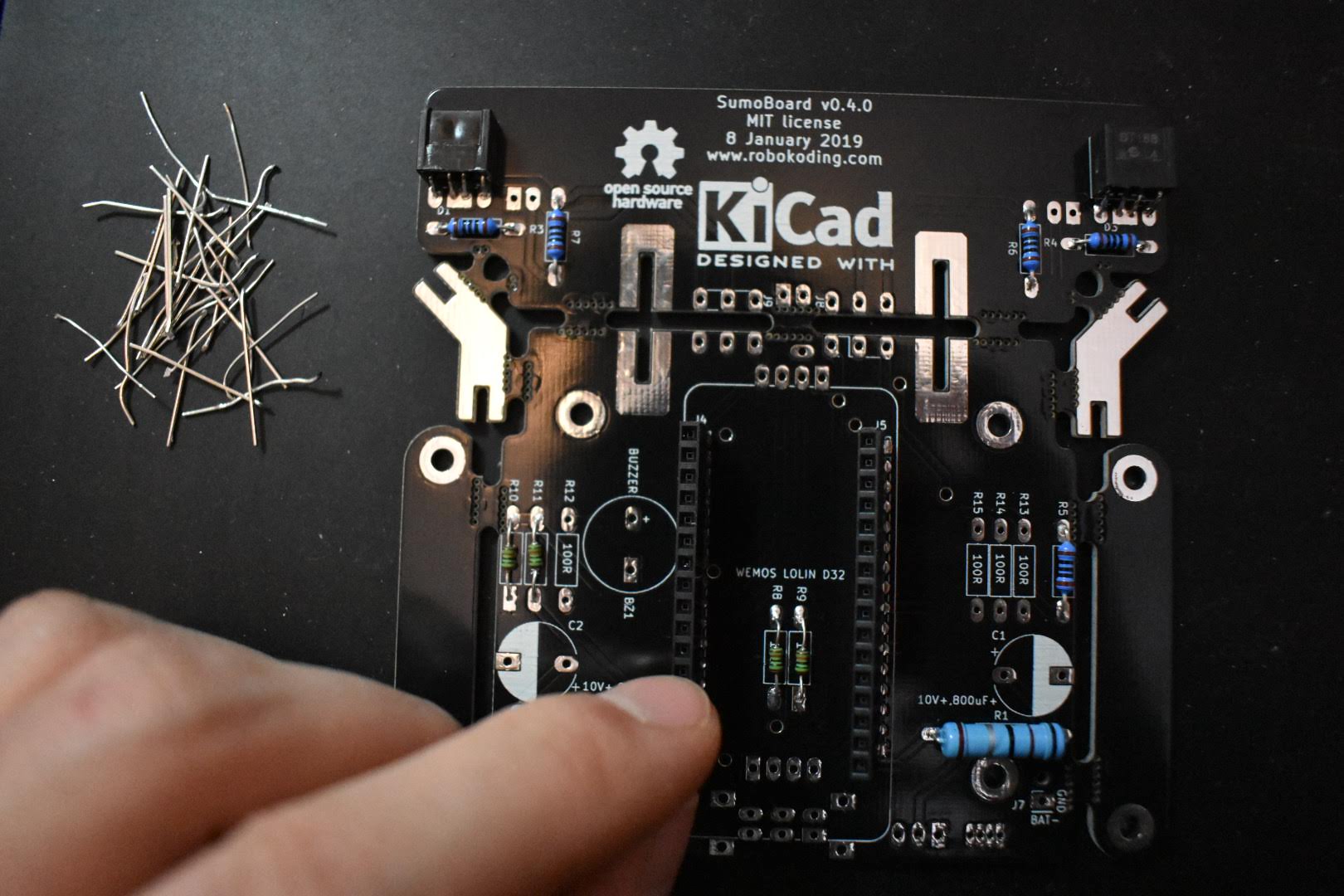
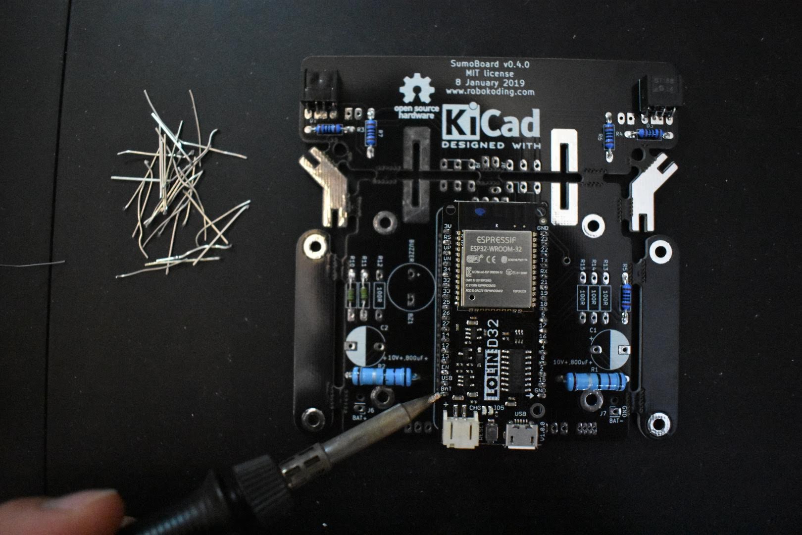
Cut the female pin header solder joints as flat as possible, so later the servomotors can fit on them better.
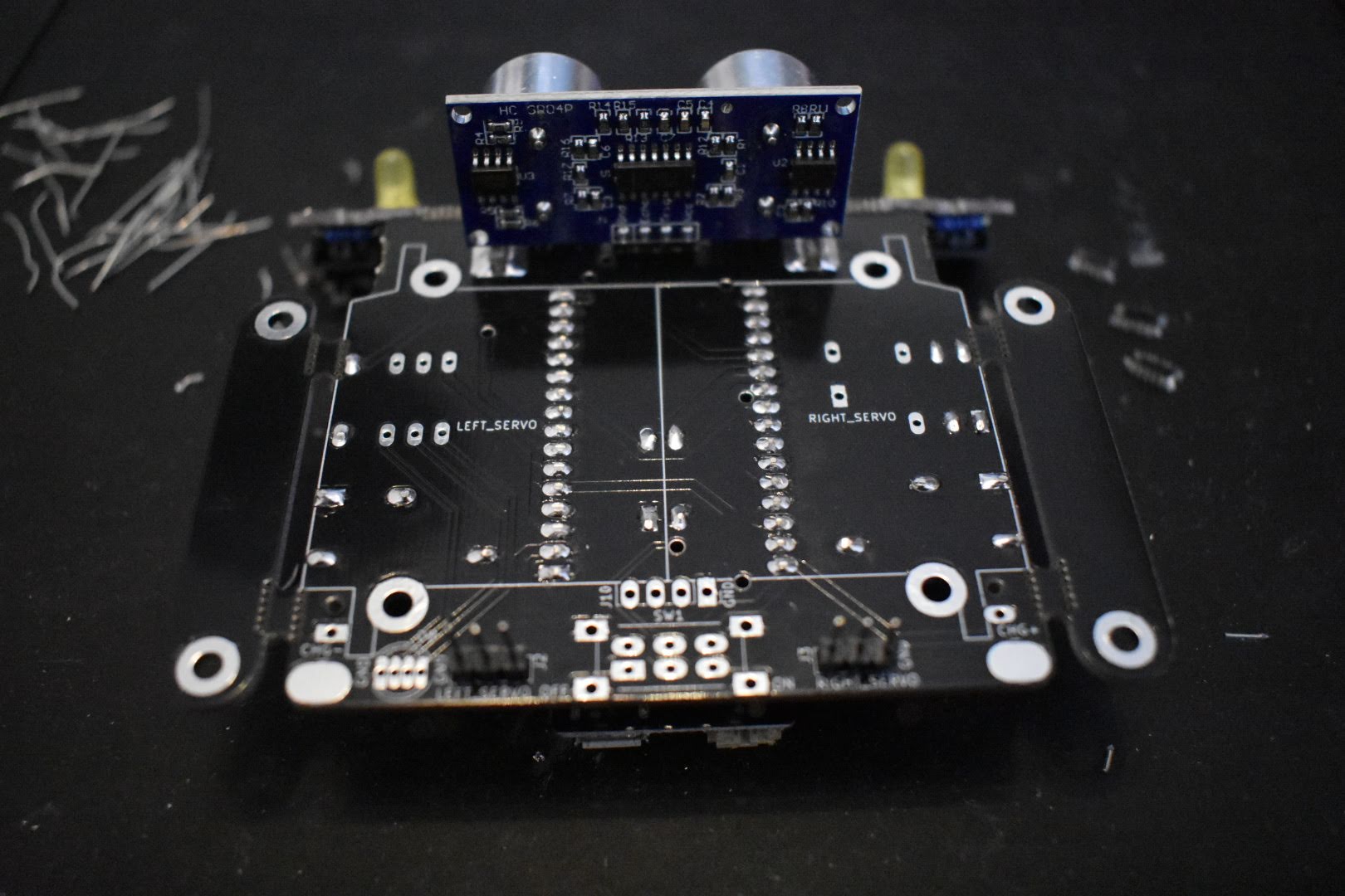
4. Solder the servomotor pin headers
The 2 pin headers (each one has 3 pins) for the servomotors go to the holes with the labels LEFT_SERVO (J2) and RIGHT_SERVO (J3). Place the pin header and solder one of its pins first. Then try to align the pin header perpendicular with the SumoBoard while reheating the previously made solder connection and pressing it from the other side. Be careful not the touch or hold from the same pin you are soldering, it will get very hot.
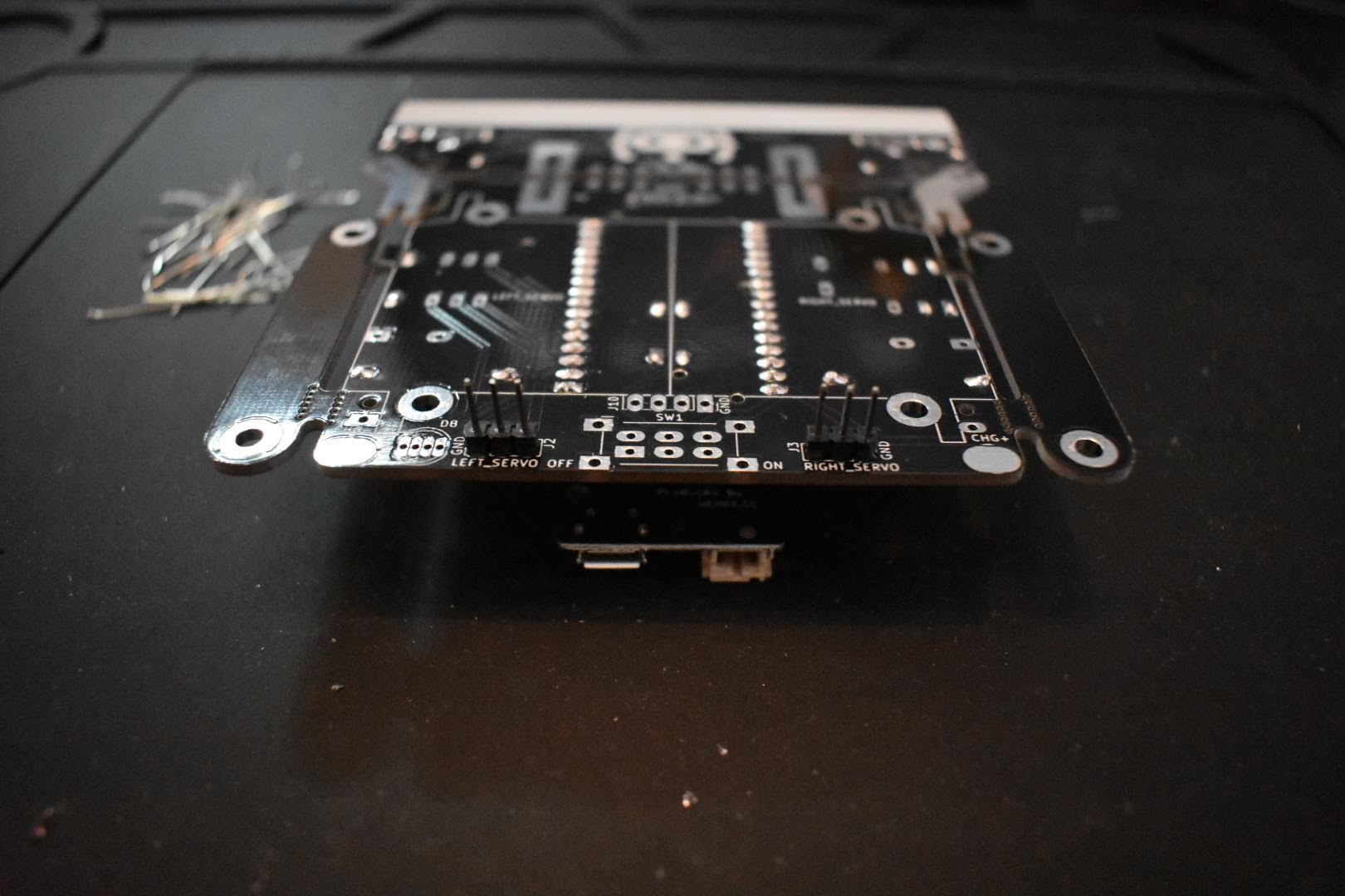
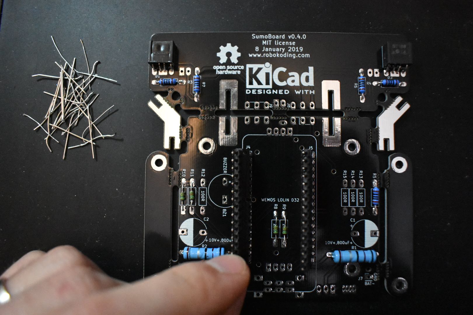
5. Solder the capacitors
The two green cylinders are the capacitors and they should be placed on the C1 and C2 markings. They have polarity, which means that you have to be careful how you place them on the board. On one side of the capacitor’s body there is a grey stripe. The capacitor’s leg from the striped side goes into the SumoBoard hole which is marked as a half circle filled with white colour. After you make sure you got the polarity right, solder the capacitors on the SumoBoard. Cut the capacitor solder joints as flat as possible, so later the servomotors can fit on them better.
6. Solder the plow
Break apart the plow and the two silver breakaway tabs. We will use those 2 tabs to connect the plow to the mainboard. After you attach everything together, solder the tabs to the plow and mainboard from both sides. Try to keep the plow pressed towards the mainboard while soldering, so it doesn’t move out of place.
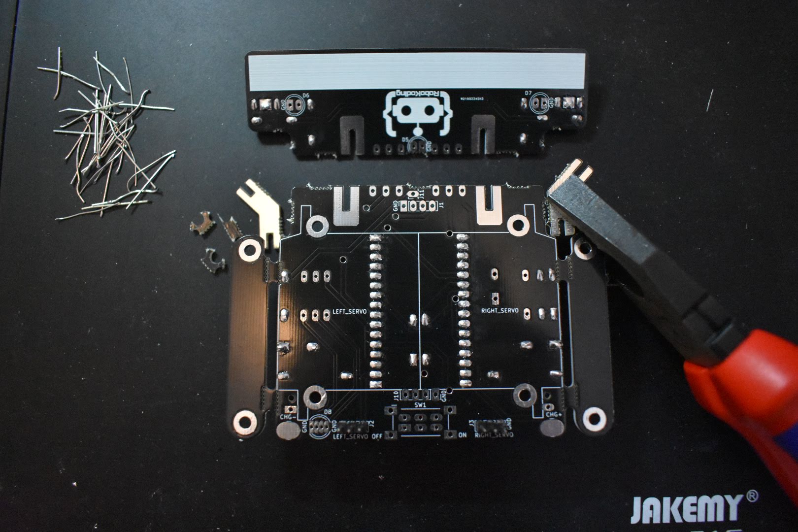

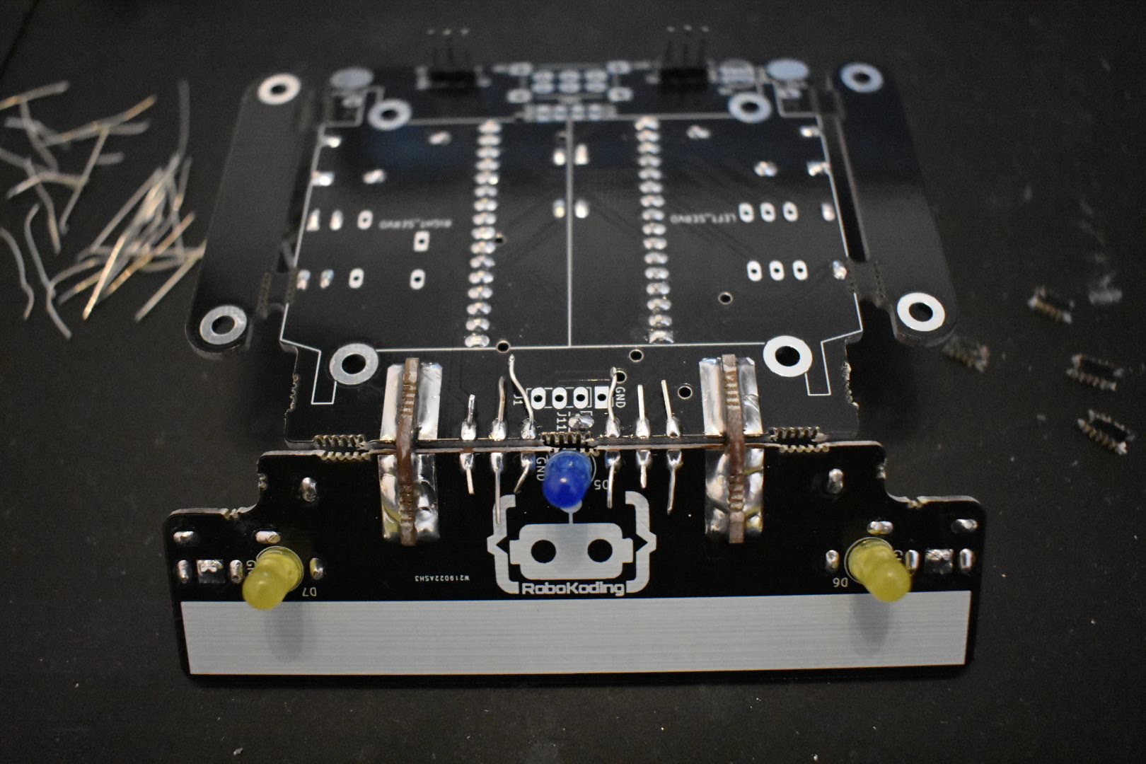
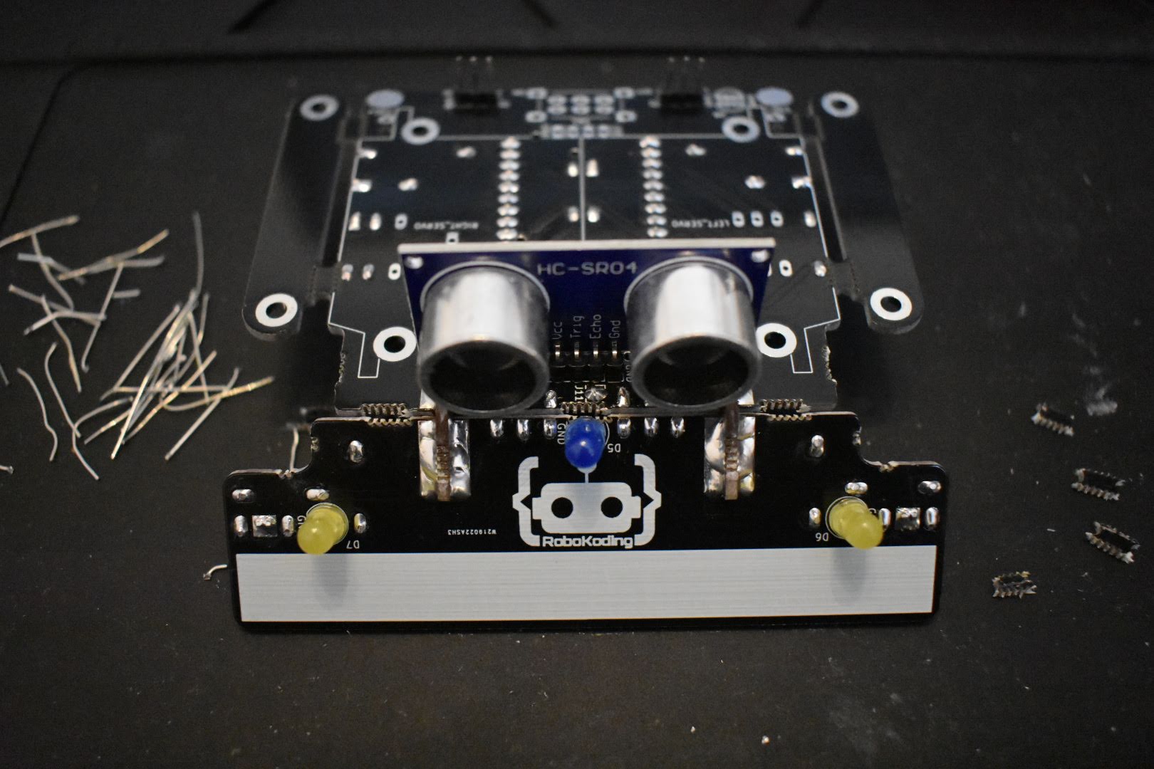
7. Solder the LEDs
Find the three LEDs - one blue and two yellow. Place the yellow ones in the holes with labels D6 and D7, while the blue one in the holes marked as D5. Be aware of the polarity again. Take a closer look and notice how the specific shape of the LED corresponds to the drawing on the board. You should place the shorter leg of the LED into the hole with a rectangular pad of the SumoBoard.
If you have SumoBoard v0.4.0 or v0.4.1 then the blue LED is placed in a more specific way. After you place the shorter leg in the hole marked with a rectangular shape, push the longer leg trough the J11 hole on the mainboard.
After you make sure the polarity has the right orientation on the board, solder the LEDs and trim the legs.
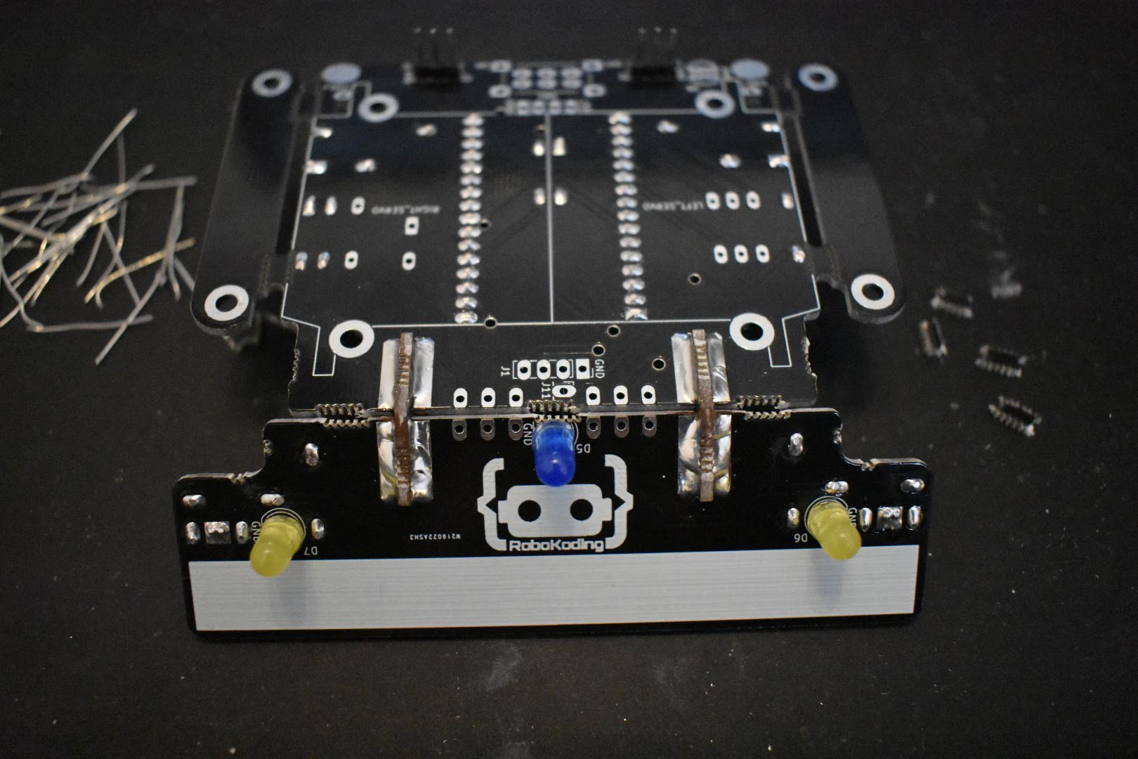
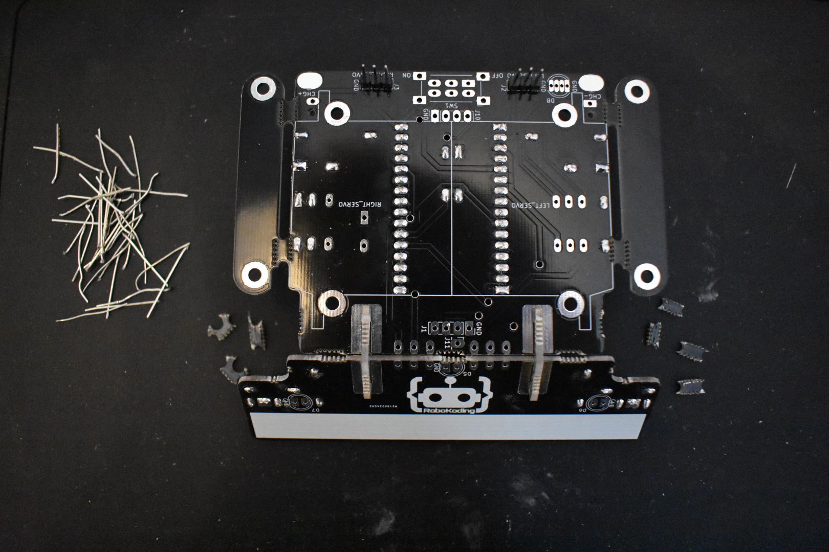
Take the remainders of the LEDs’ legs and bend them into an U shape. Then place them in the holes on the board (J8 and J9) as shown on the image below. This will establish electrical connection with the LEDs and the sensors from the plow to the mainboard. Solder the legs into place and cut the excess.
8. Solder the ultrasonic sensor
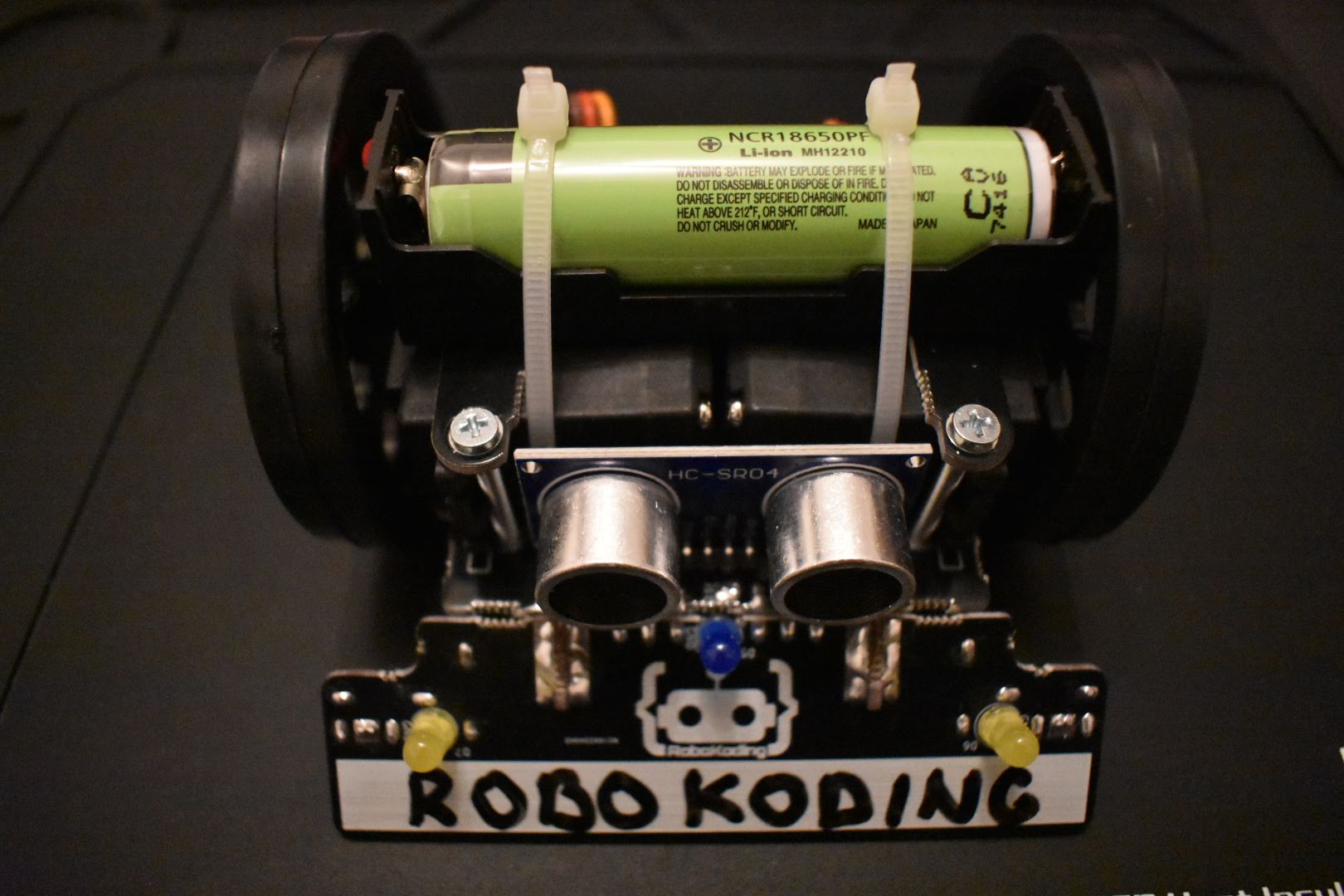
Find the ultrasonic sensor. This one helps the robot to detect objects, i.e. “to see” the opponent on the SumoRing. Push it in the holes labeled as J1 on the board and solder it into place.
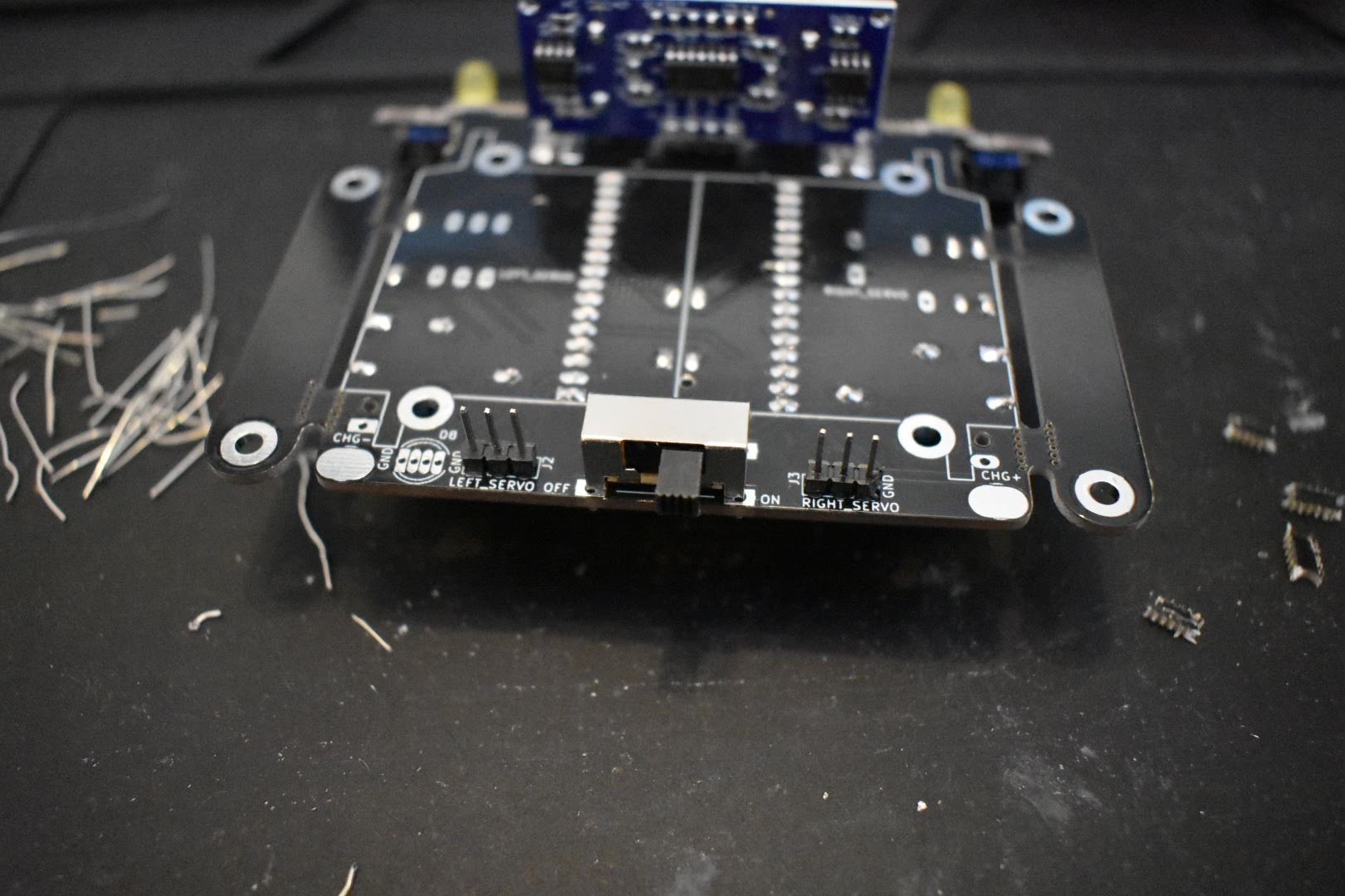
9. Solder the power button
Put the power button in the SW1 labeled holes and solder it into place.
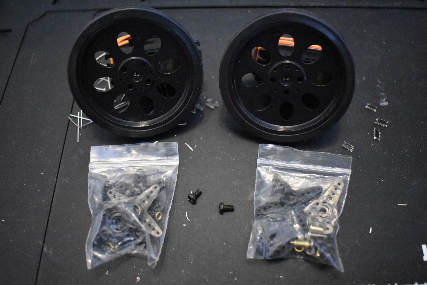
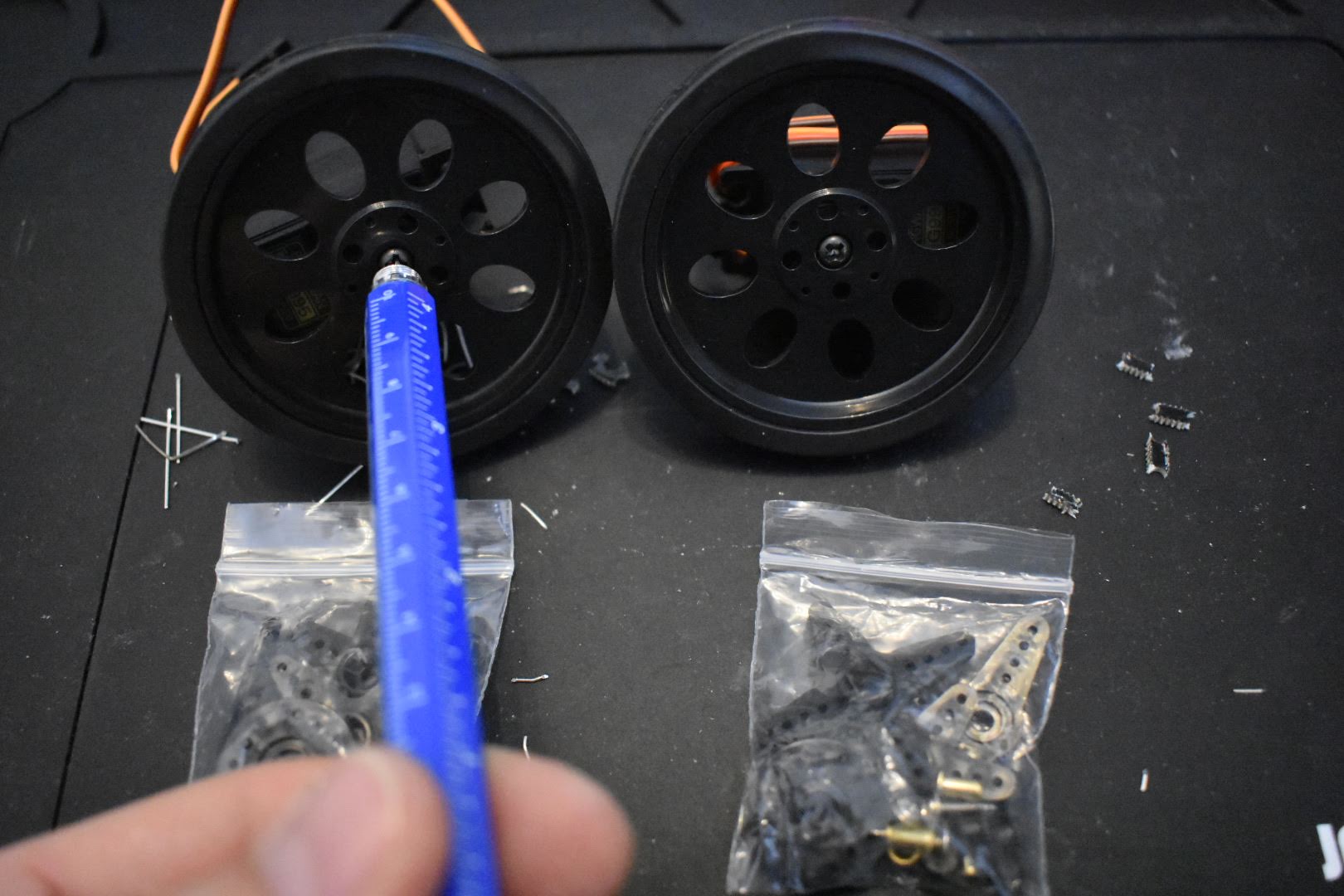
10. Assemble the servomotors
The two wheels should be attached to the servomotors, so the robot can execute the movement commands. Find the two black screws from the bag and screw them to the wheels.
Break away the 2 remaining tabs on each side of the SumoBoard.
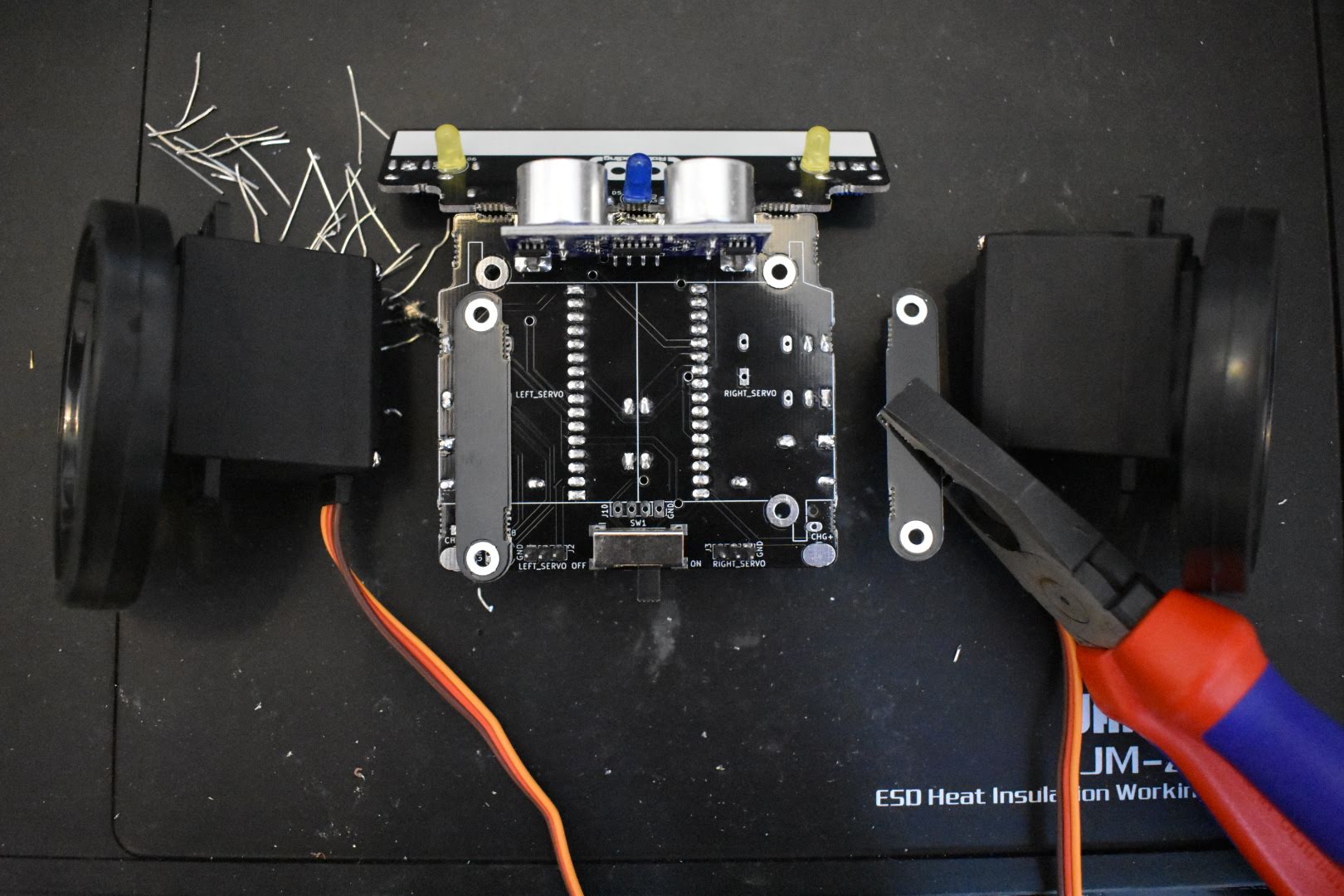
If you have white zip ties: place them under the servomotors on the SumoBoard on top of the labels LEFT_SERVO and RIGHT_SERVO.
If you have black cable ties: then you can place them either under the servomotors or under the breakaway tabs.
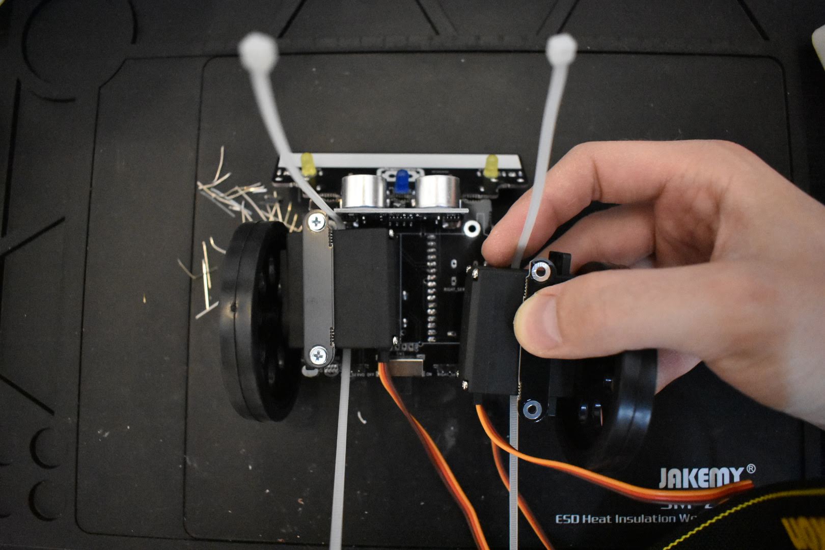
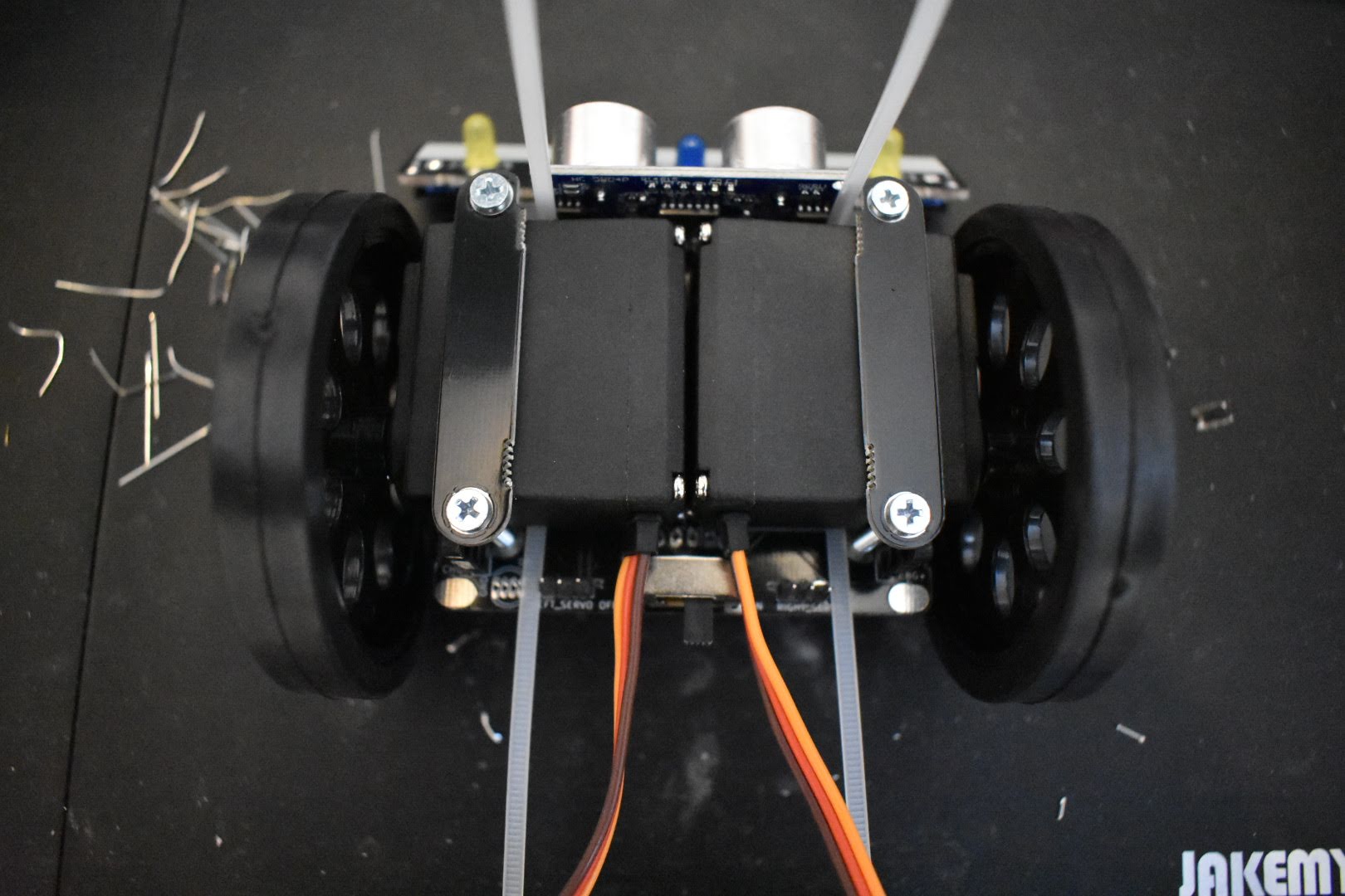
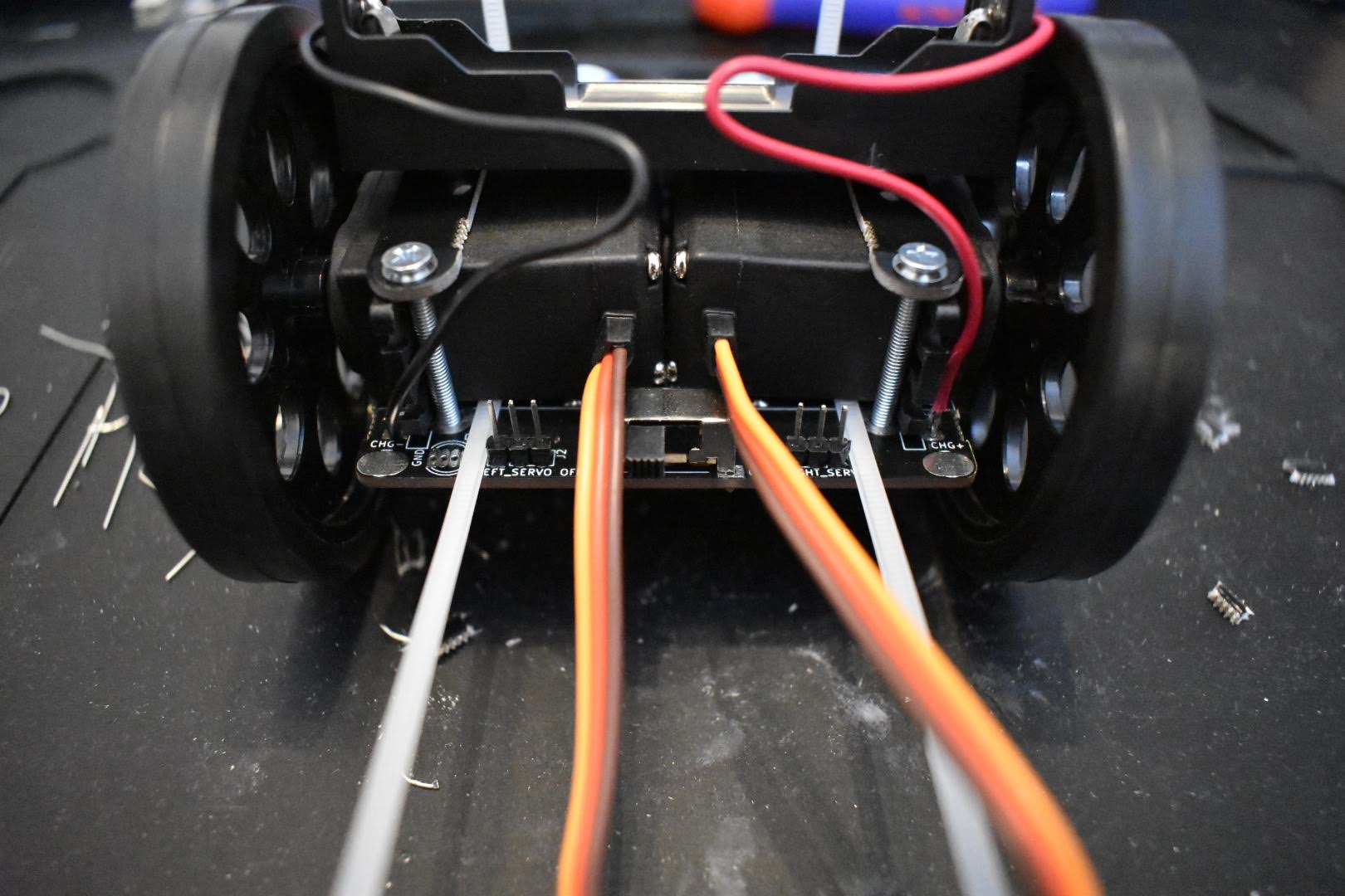
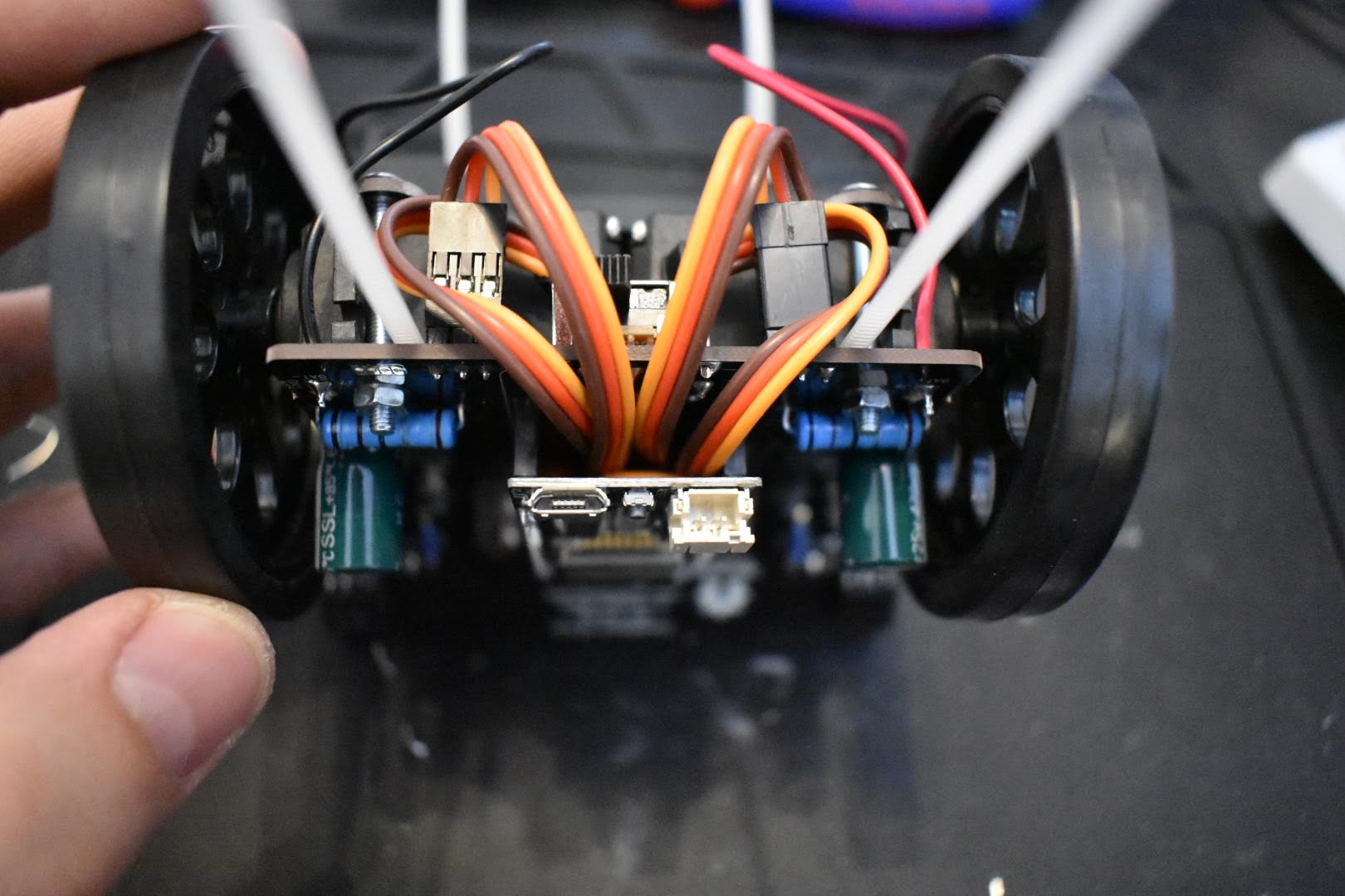
The positioning of the servomotors is important - their cables should go towards the back of the robot, where the power switch is. Afterwards, place the black breakaway tabs on top of the servos. Insert the screws from up, the nuts from below and then screw them together.
11. Connect the battery
Cut the ends of the black and red cables a bit.
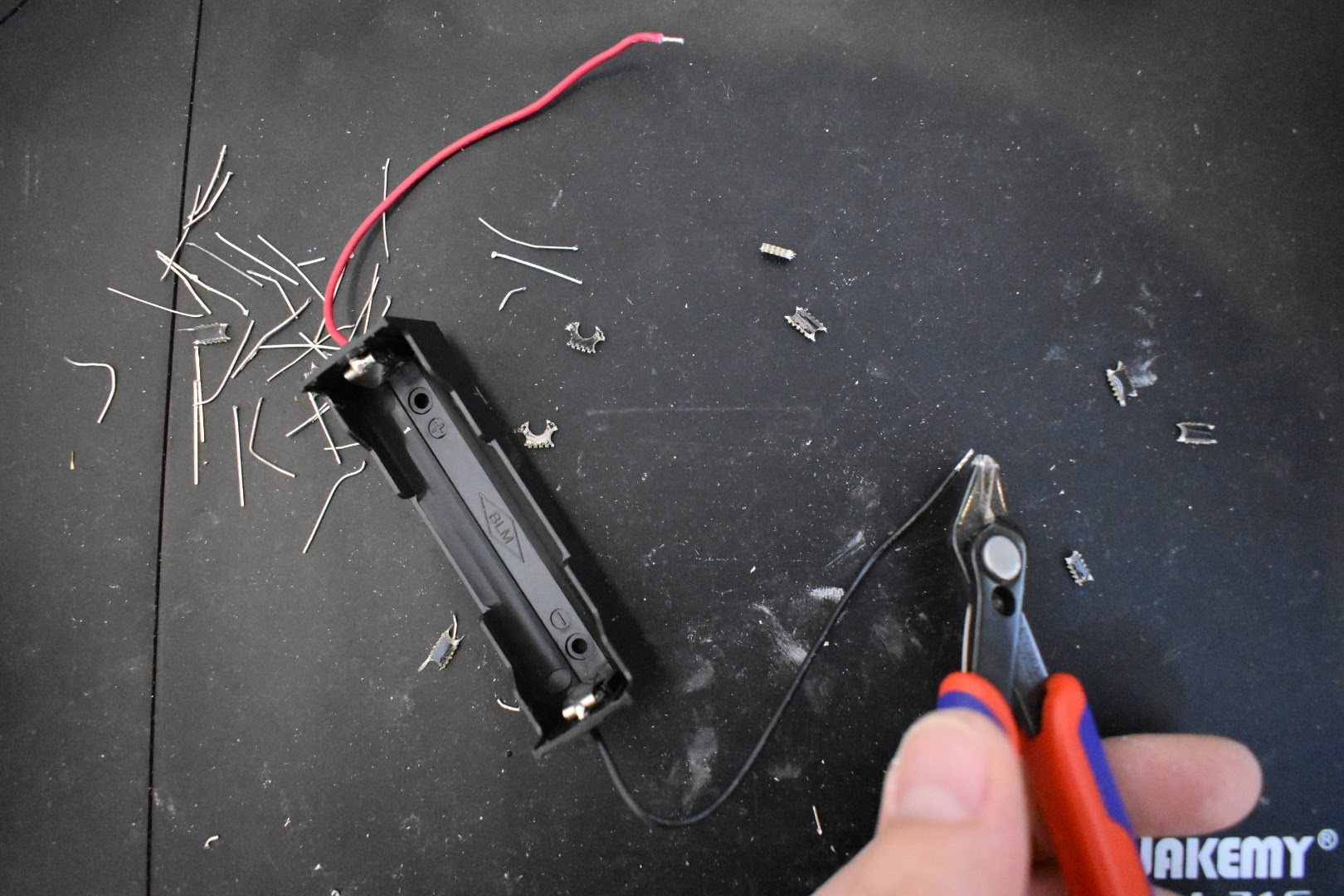
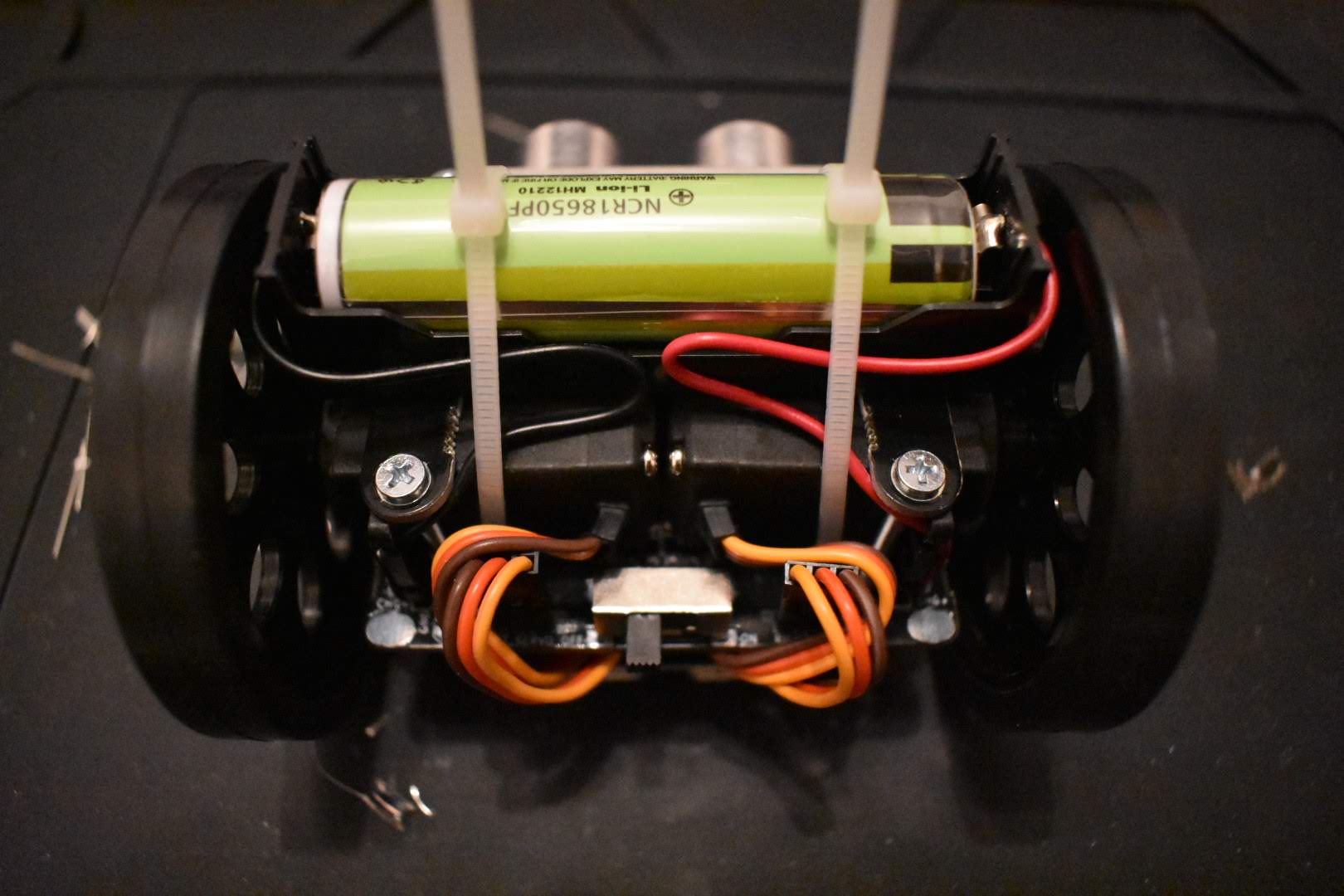
Put the black and red battery holder wire trough the holes near the pads labeled BAT+ and BAT- (J6, J7). Then bend them to form a little U shaped loop into the pad J6, J7 holes and solder them. When this is done, you can put the servo motor cables under the microcontroller, as shown in the pictures below.
Then insert the battery, be careful to insert it the right way. The bigger pad on the battery is - (GND) and goes to the side with the black cable. The smaller pad is + and goes to the side of the red cable.
Next pull tight the white zip ties or the black cable ties around the battery.
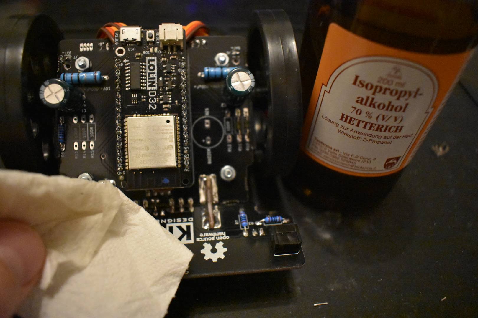
13. Clean the PCB
Use any strong alcohol to clean the PCB with a toothbrush or wipe.
TIP: You can add some hot glue or other means to make the wheel have more friction.
Finally add a name on front of your SumoRobot. Congratulations, your done with assembling your SumoRobot!
Usage instructions
To turn ON the SumoRobot slide the big power switch to the right (ON). To turn the SumoRobot OFF, slide the big power switch to the left (OFF).
In order to charge the SumoRobot, plug the micro USB into the SumoRobot’s microcontroller. The red charging LED will light up. The SumoRobot can be charged in both ON and OFF state. Once the battery is full the red LED light will turn OFF.
Uploading / updating the SumoFirmware is possible with the SumoManager app. Keep in mind to use the SumoManager, the SumoRobot has to be turned ON. The blue LED under the SumoRobot will blink when it’s not connected to the SumoInterface, once connected the blue LED will be steady ON.
The yellow LED lights indicate if the SumoRobot is seeing a line. This works only on the SumoField or on a white paper with a thick black line. There are two line sensors under the plow of the SumoRobot, on the left and right. You can print your own SumoField on a A0 paper at a local print shop, download it here.
The blue LED light indicates if the SumoRobot sees something in front of it. It sees about 40cm in distance.
Debugging problems
In case you are facing some problems with the SumoRobot you can contact letstalk@robokoding.com In case you are interested to debug problems yourself you can head over to GitHub to find all the design files and software.