SumoHardware v0.3.X
Assembly instructions
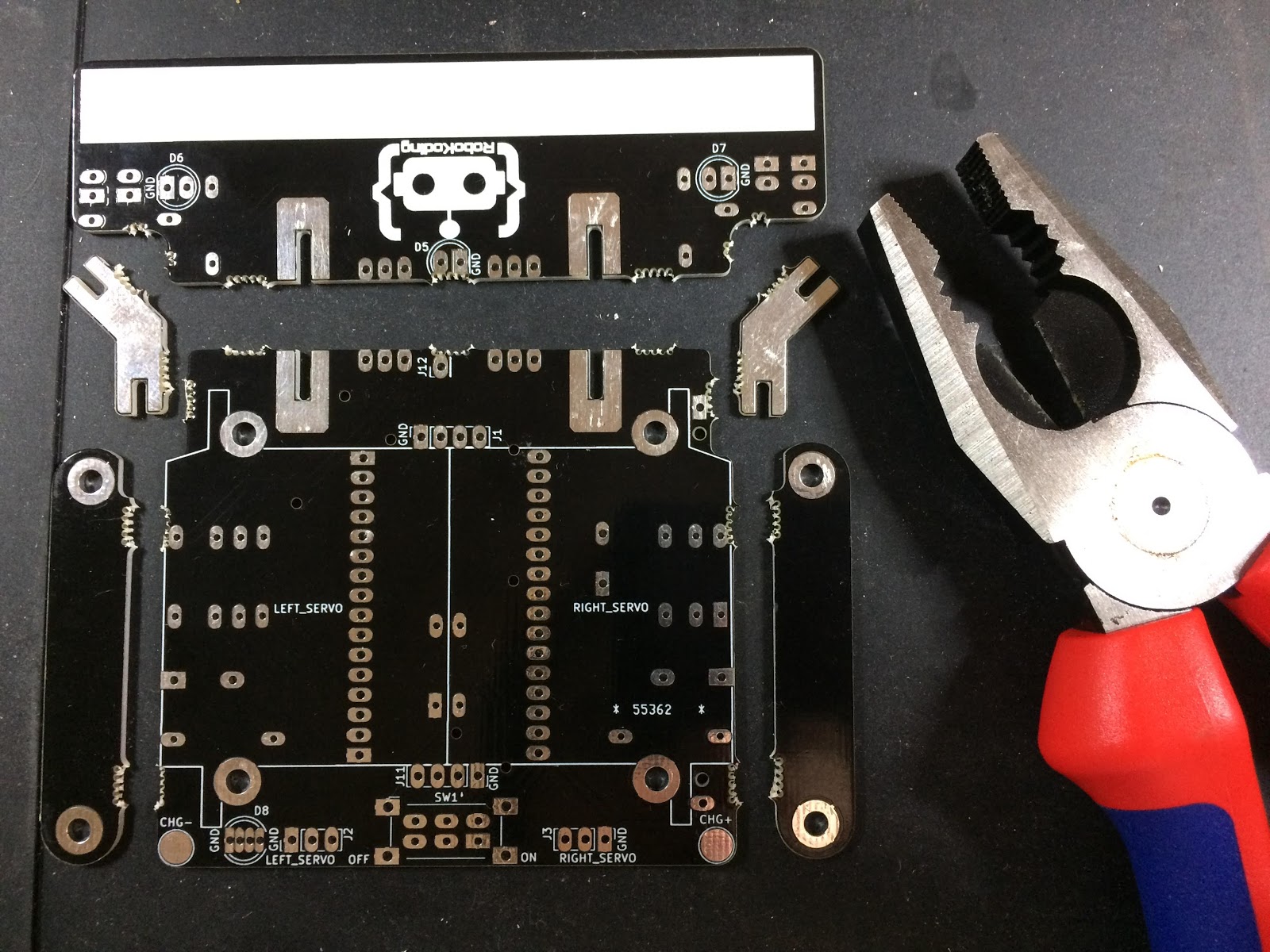
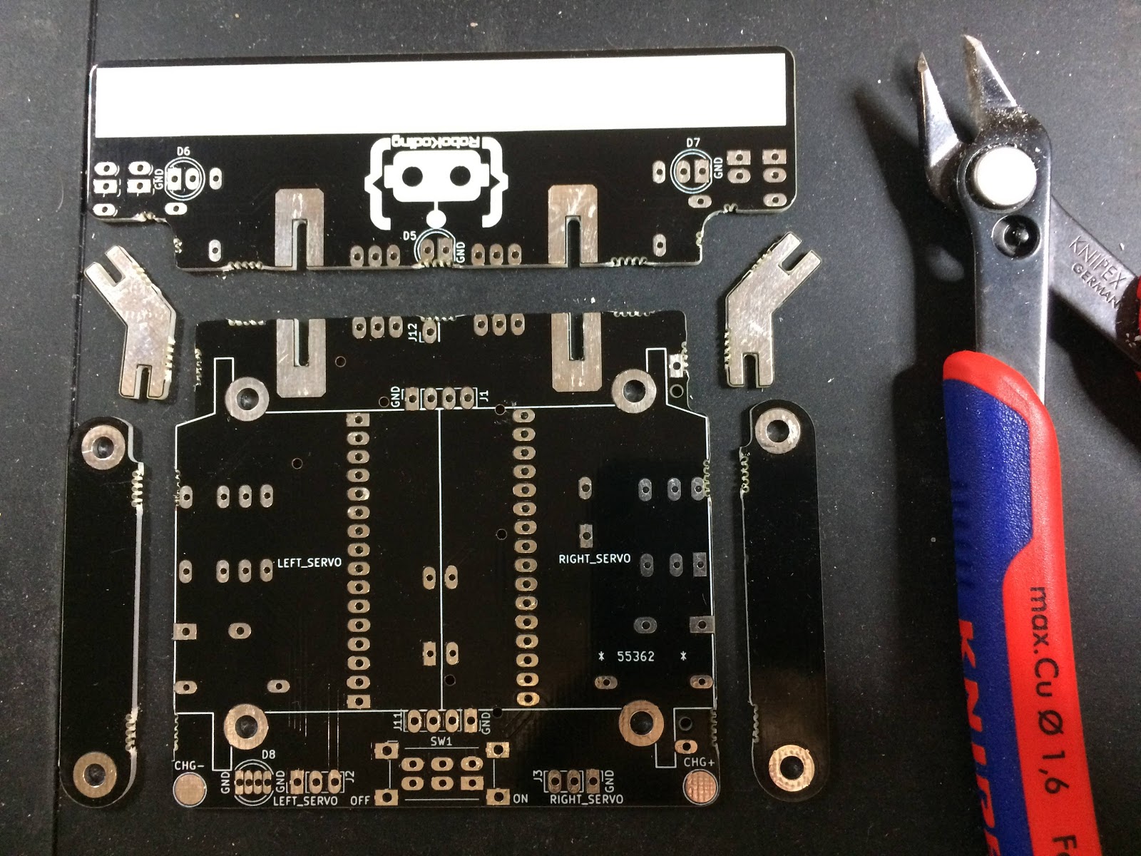
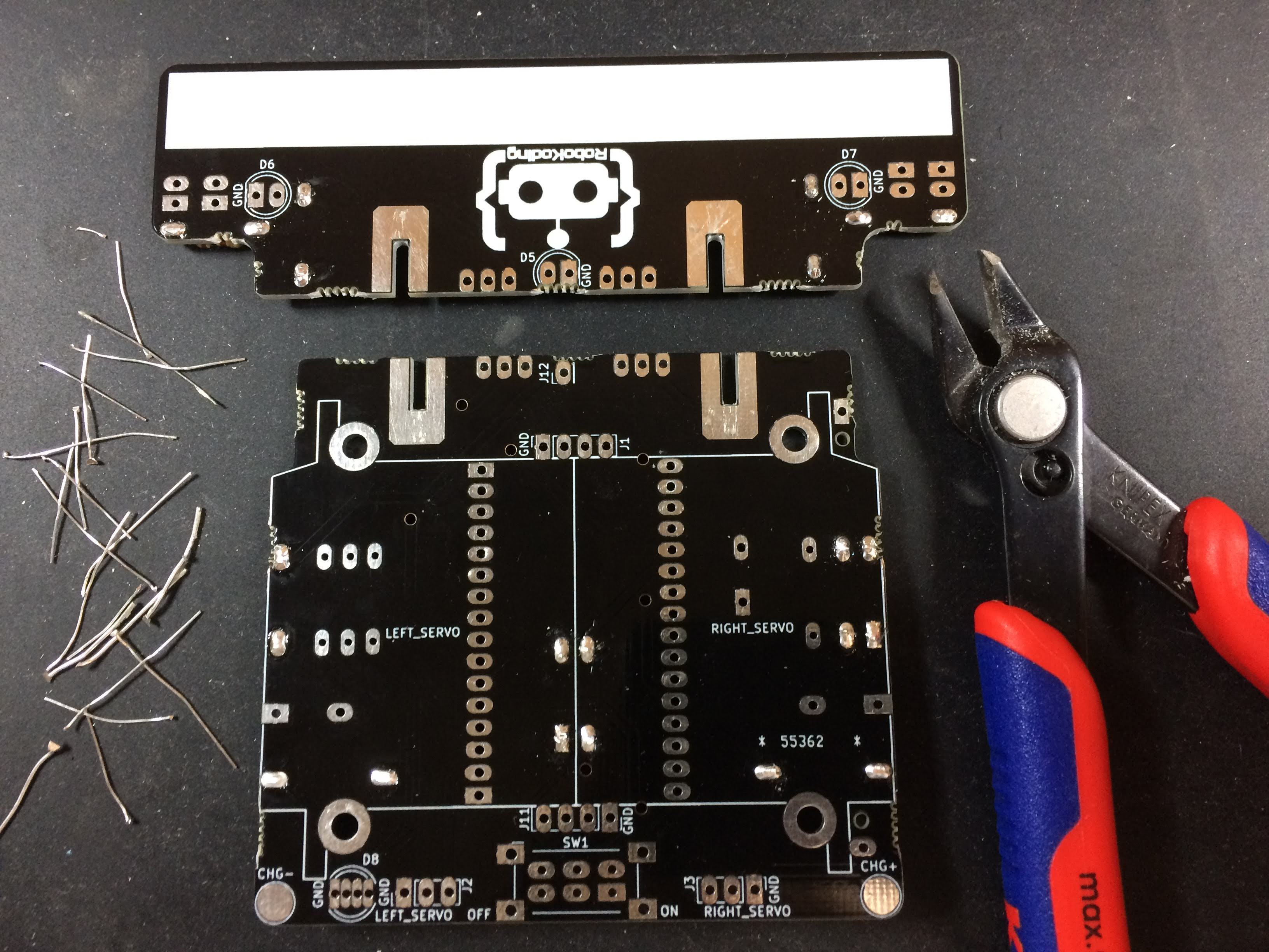
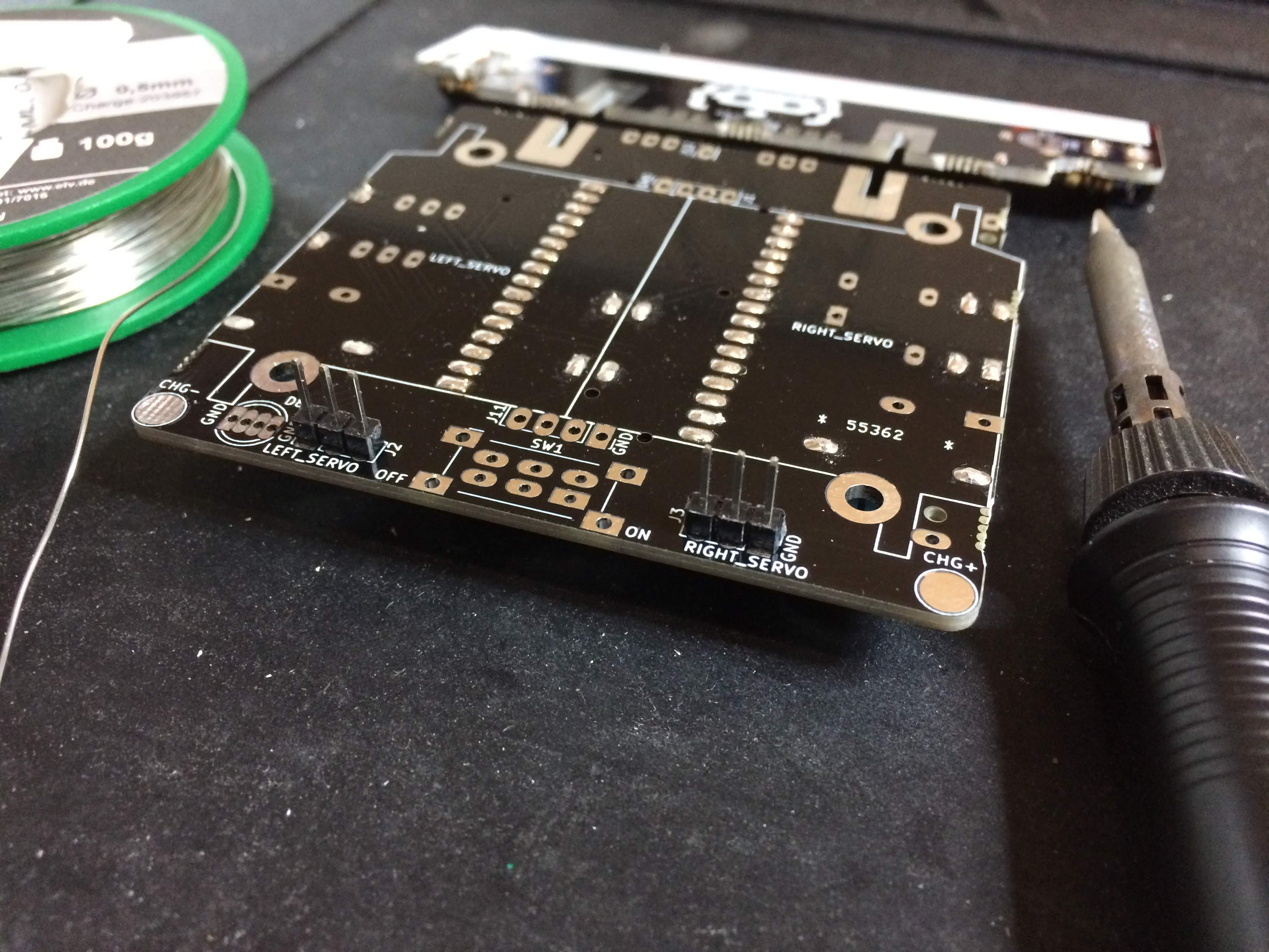
1. Break the PCB apart
Start by taking the black board that has RoboKoding’s logo on it. That is the PCB (meaning “printed circuit board”) of the SumoRobot, where you will solder all the different components. If you look closer, you will notice tiny holes around the board. Those are the breakaway tabs that you need to separate into individual parts. Using pliers, carefully break off each part. After you separate all the parts, use a tool to smoothen the rough edges. You can use a wire cutter, scissors, a hand file or sand paper.
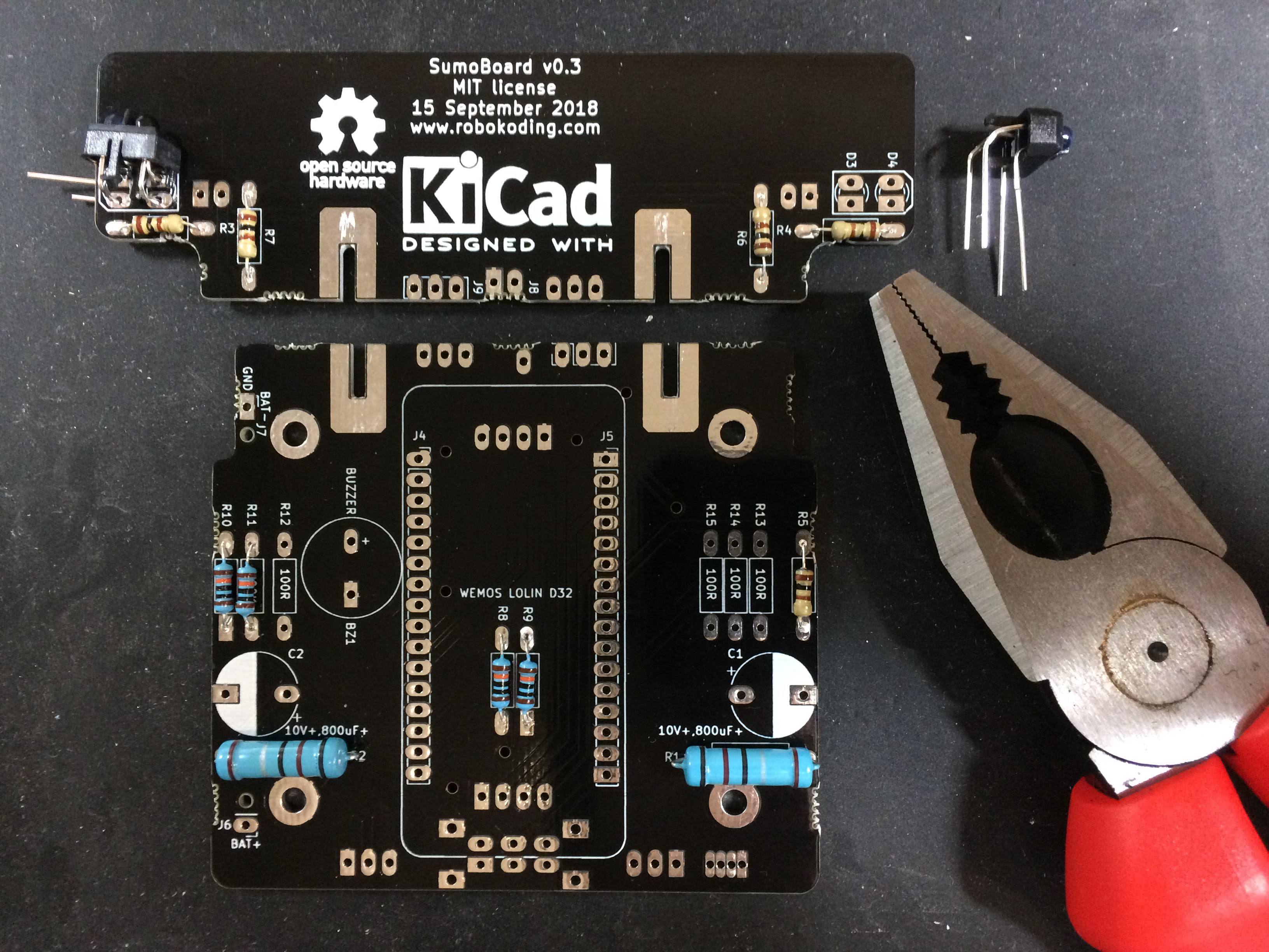
2. Solder the resistors
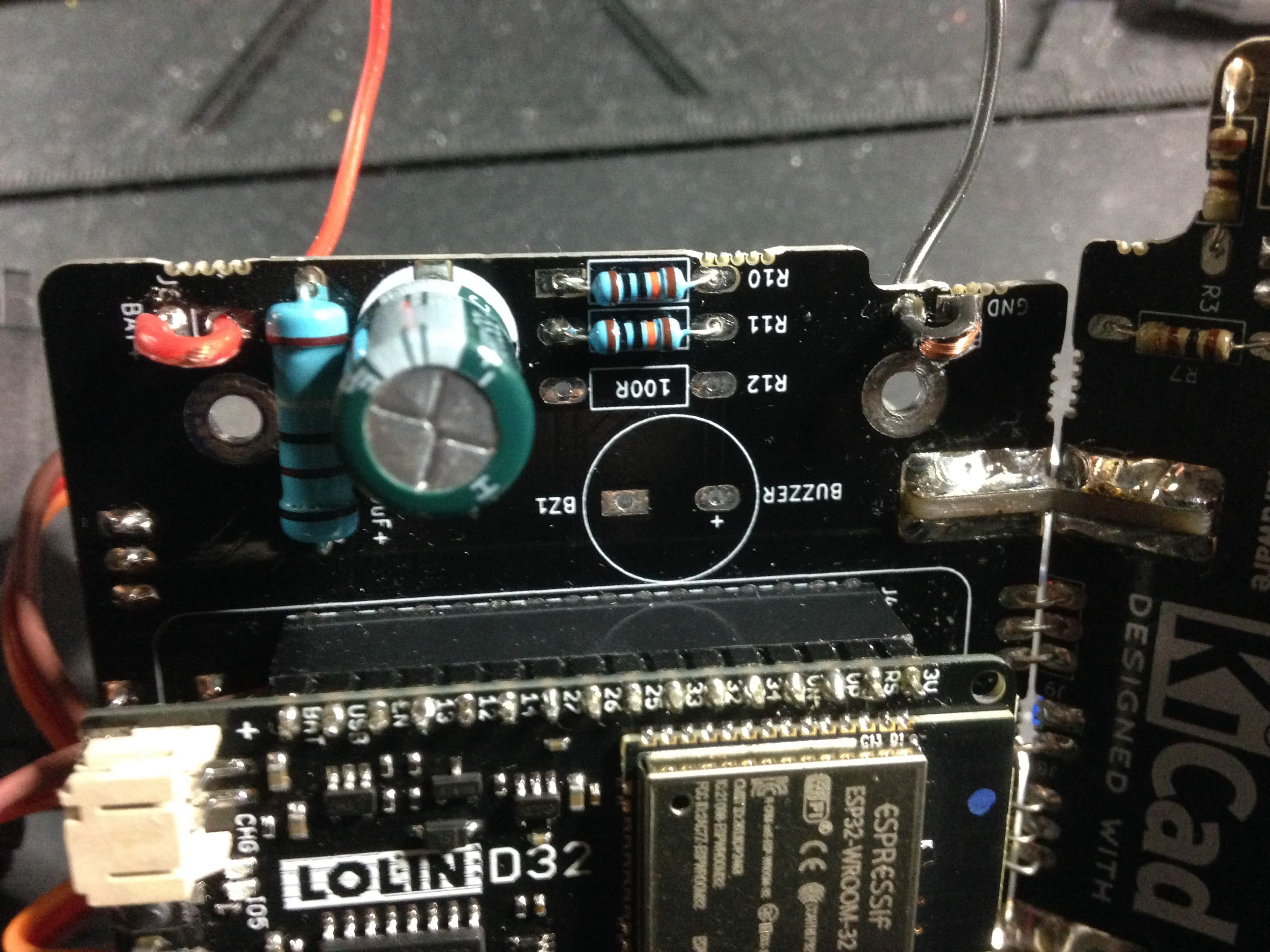
There are 11 resistors in the kit: 2 big blue, 5 small beige and 4 small blue resistors - all of them with different colour codes indicating the resistance value. Flip the SumoBoard on its backside and place them according to the numbers shown below:
Big blue resistors > R1, R2 = 0.1 ohm
Small beige resistors > R3, R4, R5, R6, R7 = 100 ohm
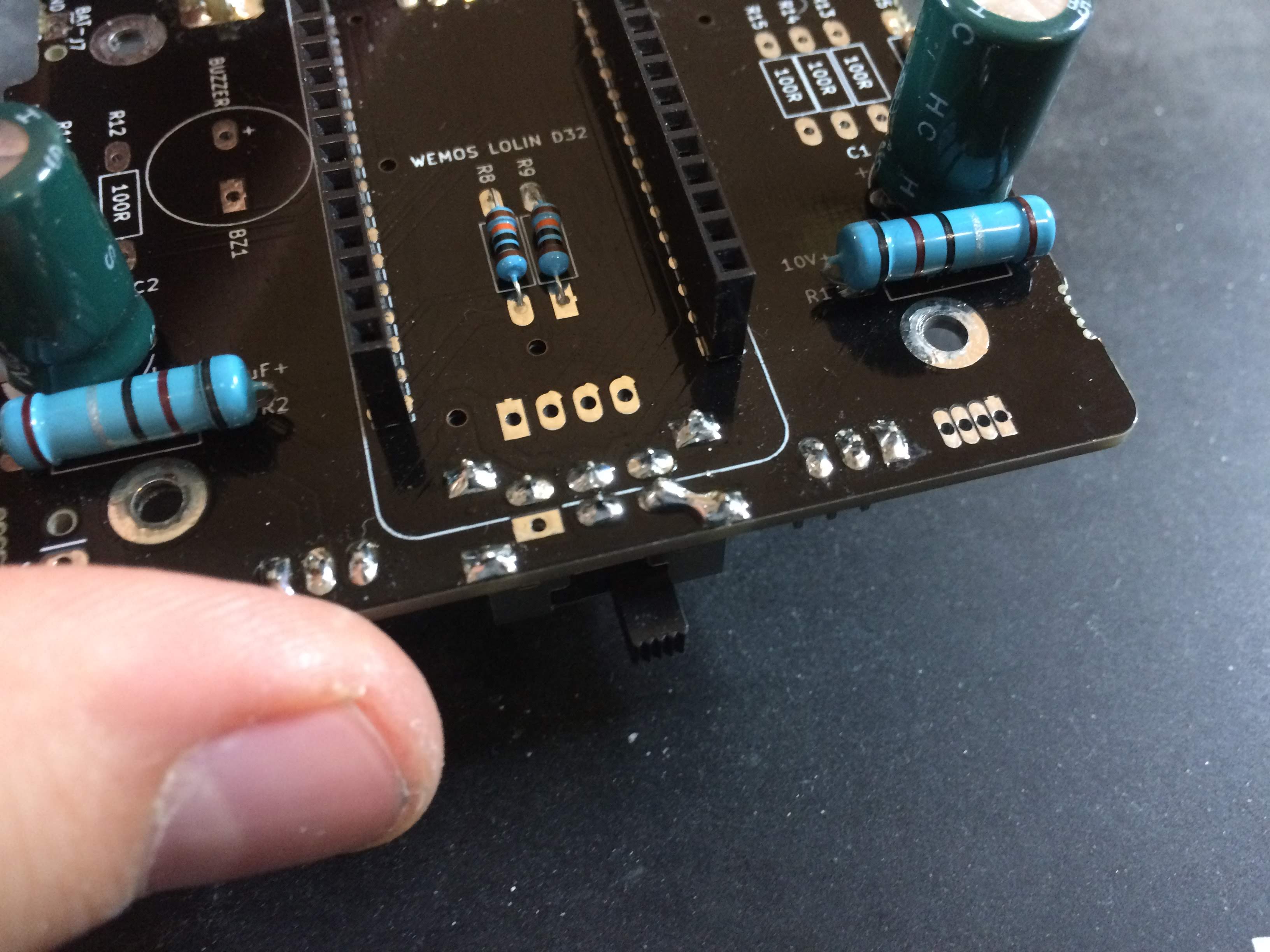
Small blue resistors > R8, R9, R10, R11 = 100K ohm
Bend the resistor legs 90 degrees and place them on the SumoBoard. You can place and solder them one by one, or all together. They don’t have polarity, which means that you can place them in any of orientation on the board.
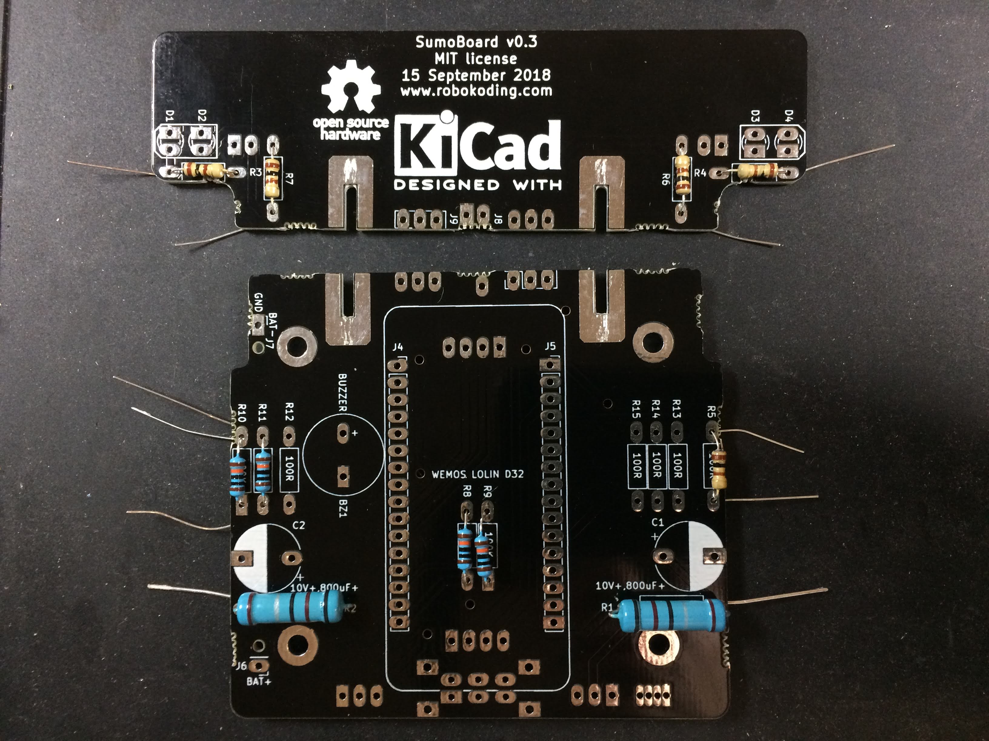
Cut the remainder of the resistor’s legs and keep the remainders on the side, for a later step.
3. Solder the phototransistors
Find the two phototransistors - these are the light sensors that help the SumoRobot detect the line on the SumoRing. They are polarized, therefore pay close attention to the white drawing on the SumoBoard. The drawing corresponds to the shape of the phototransistor, therefore showing you the right way to place it on the board. Bend the legs 90 degrees, place them on the board (labels: D1, D2 and D3, D4) and then solder them.
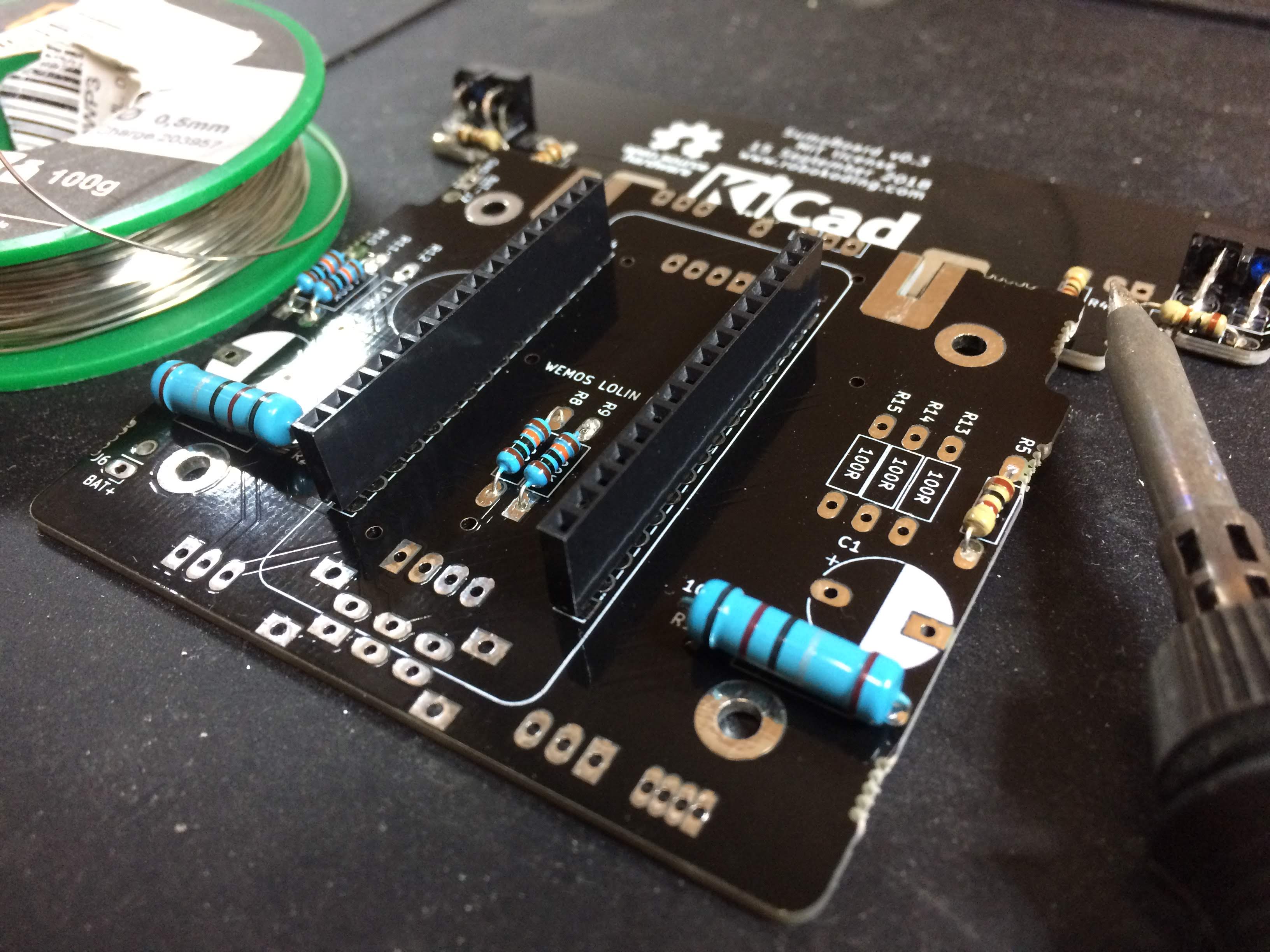
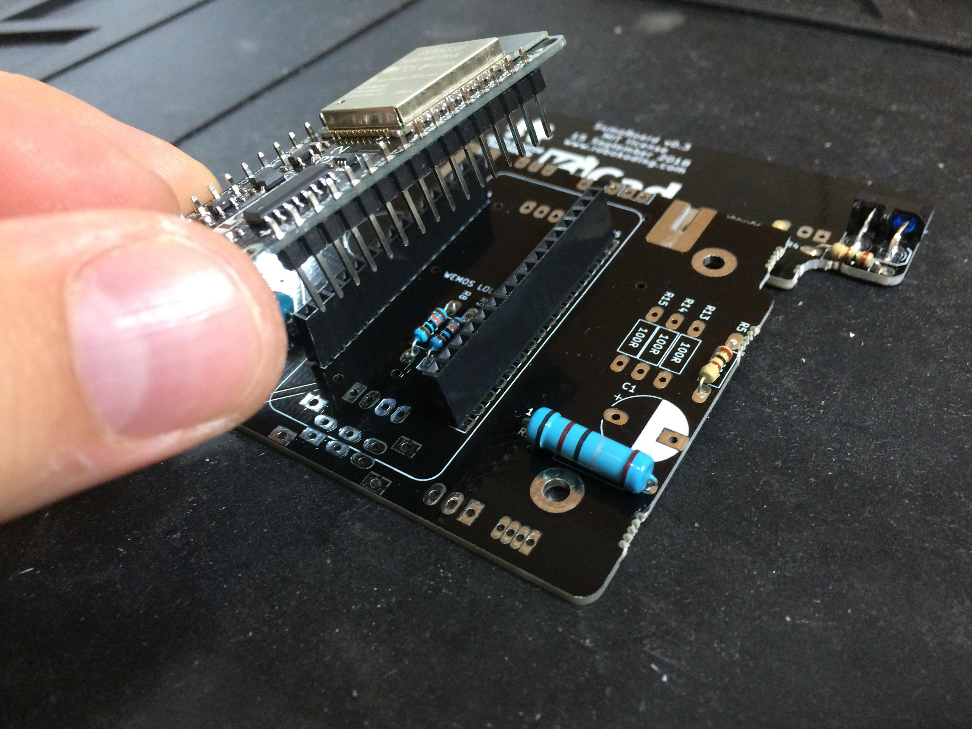
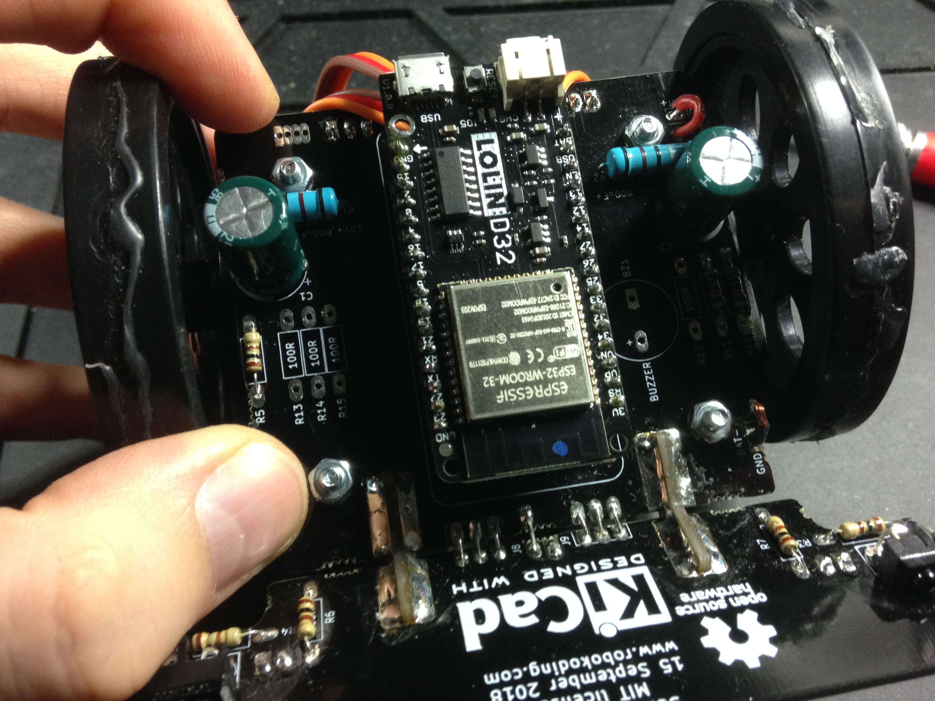
4. Solder the microcontroller
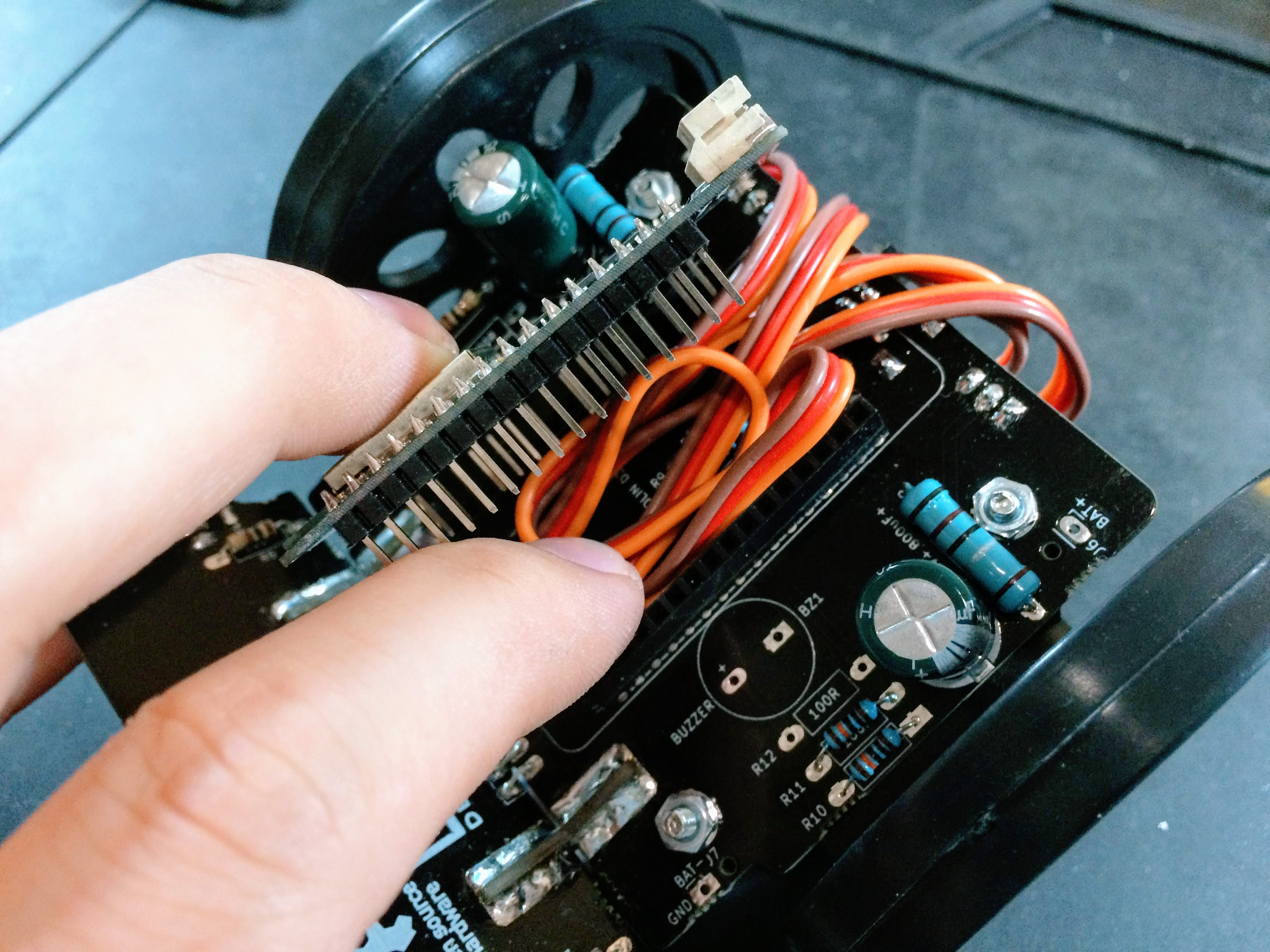
For this step you need the microcontroller, the pair of male pin headers and the pair of female pin headers. Place the female pin headers on the markings J4 and J5 on the board. Afterwards put the male pin headers into the microcontroller and place them on the board, into the female pin headers. Then solder the male pin headers to the microcontroller and the female pin headers to the SumoBoard.
5. Solder the servomotor pin headers
IMPORTANT! Check closely where you place the pin headers. On the other side of the SumoBoard there are other holes where it also fits.
The 2 pin headers for the servomotors go to the holes with the labels LEFT_SERVO (J2) and RIGHT_SERVO (J3). Place the pin header and solder one of its pins first. Then try to align the pin header 90 degrees with the SumoBoard while reheating the previously made solder connection and pressing it from the other side.
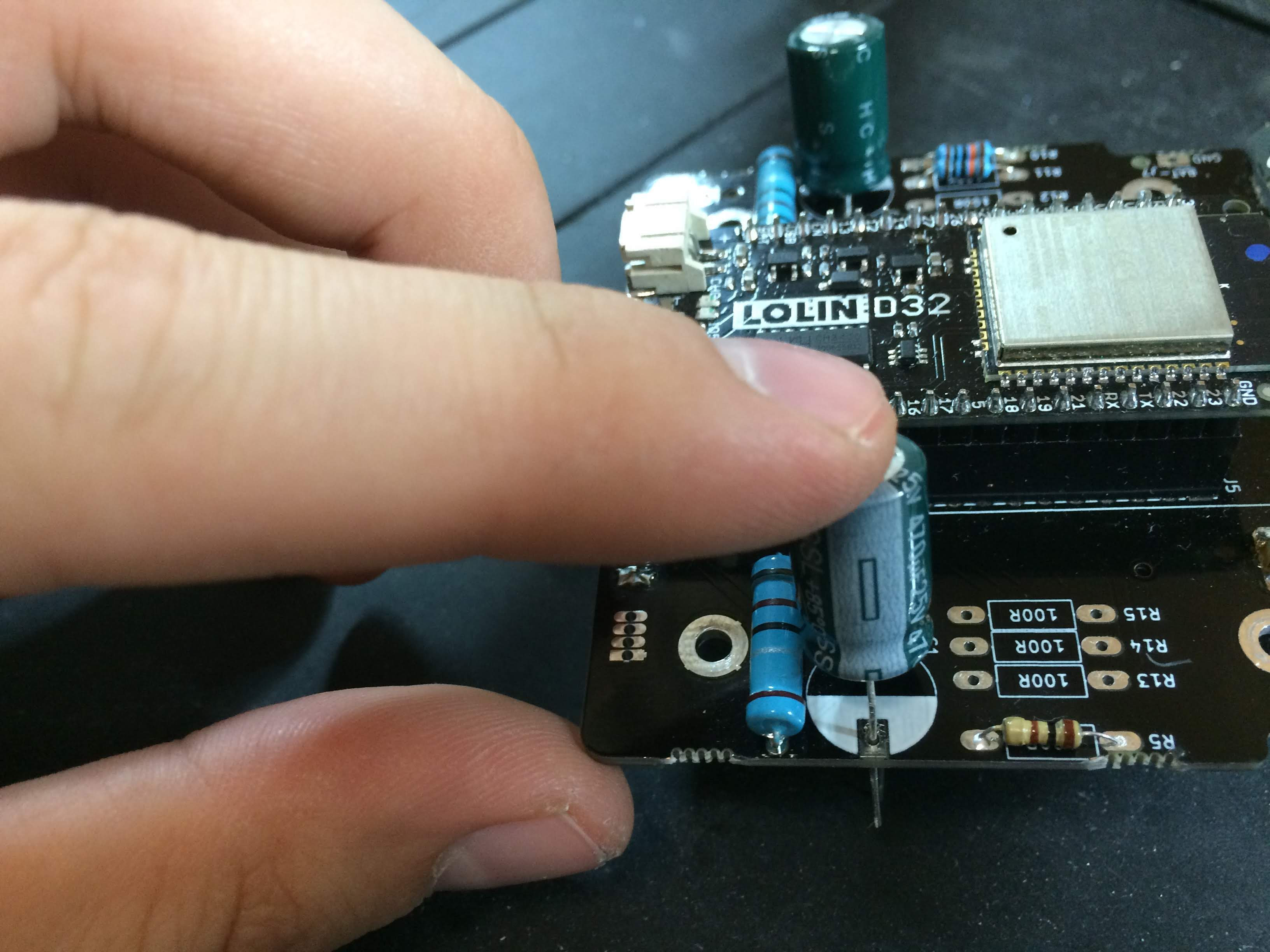
6. Solder the capacitors
The two green cylinders are the capacitors and they should be placed on the C1 and C2 markings. They have polarity, which means that you have to be careful how you place them on the board. On one side of the capacitor’s body there is a grey stripe. The capacitor’s leg from the striped side goes into the SumoBoard hole which is marked as a half circle filled with white colour. After you make sure you got the polarity right, solder the capacitors on the SumoBoard.
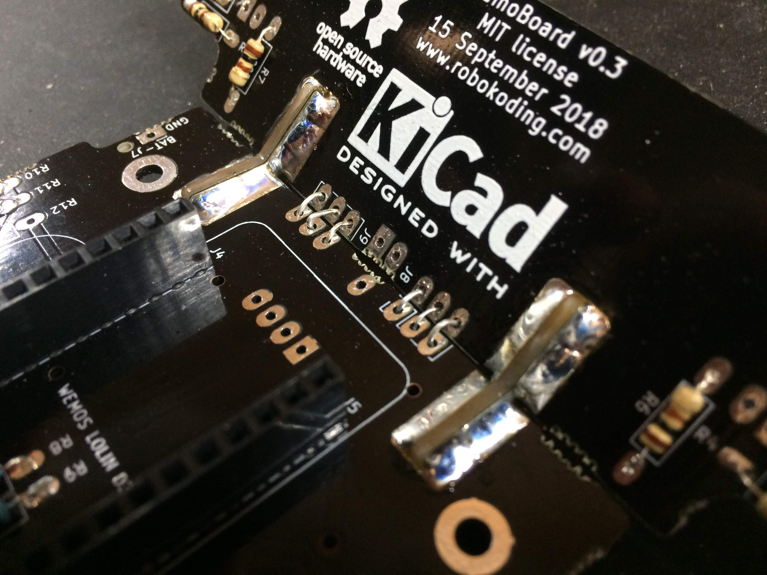
7. Solder the plow
Find the plow and the two silver breakaway tabs from the first step. We will use those to connect the plow to the main board. After you attach everything together, apply solder on both sides of the board.
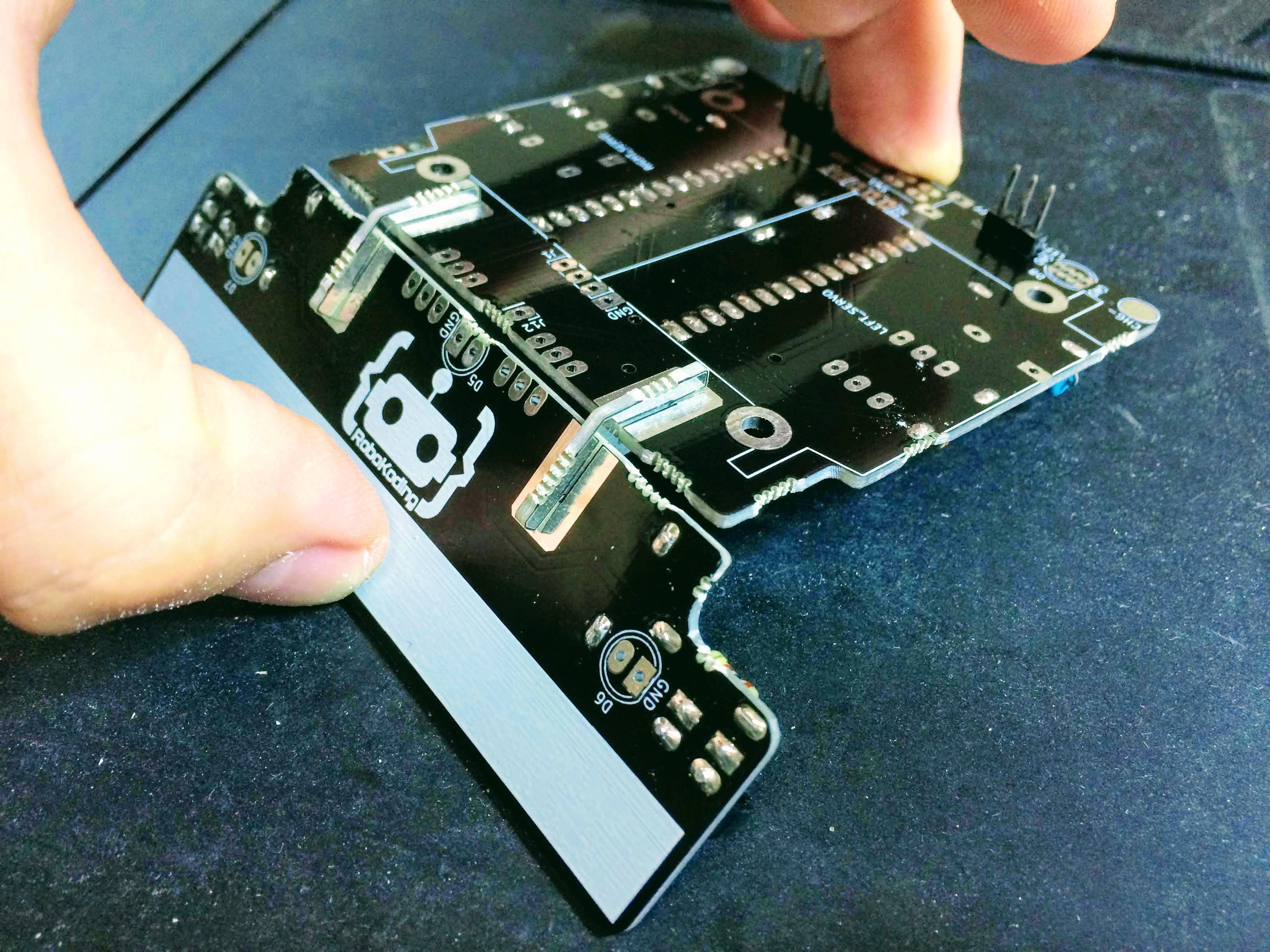
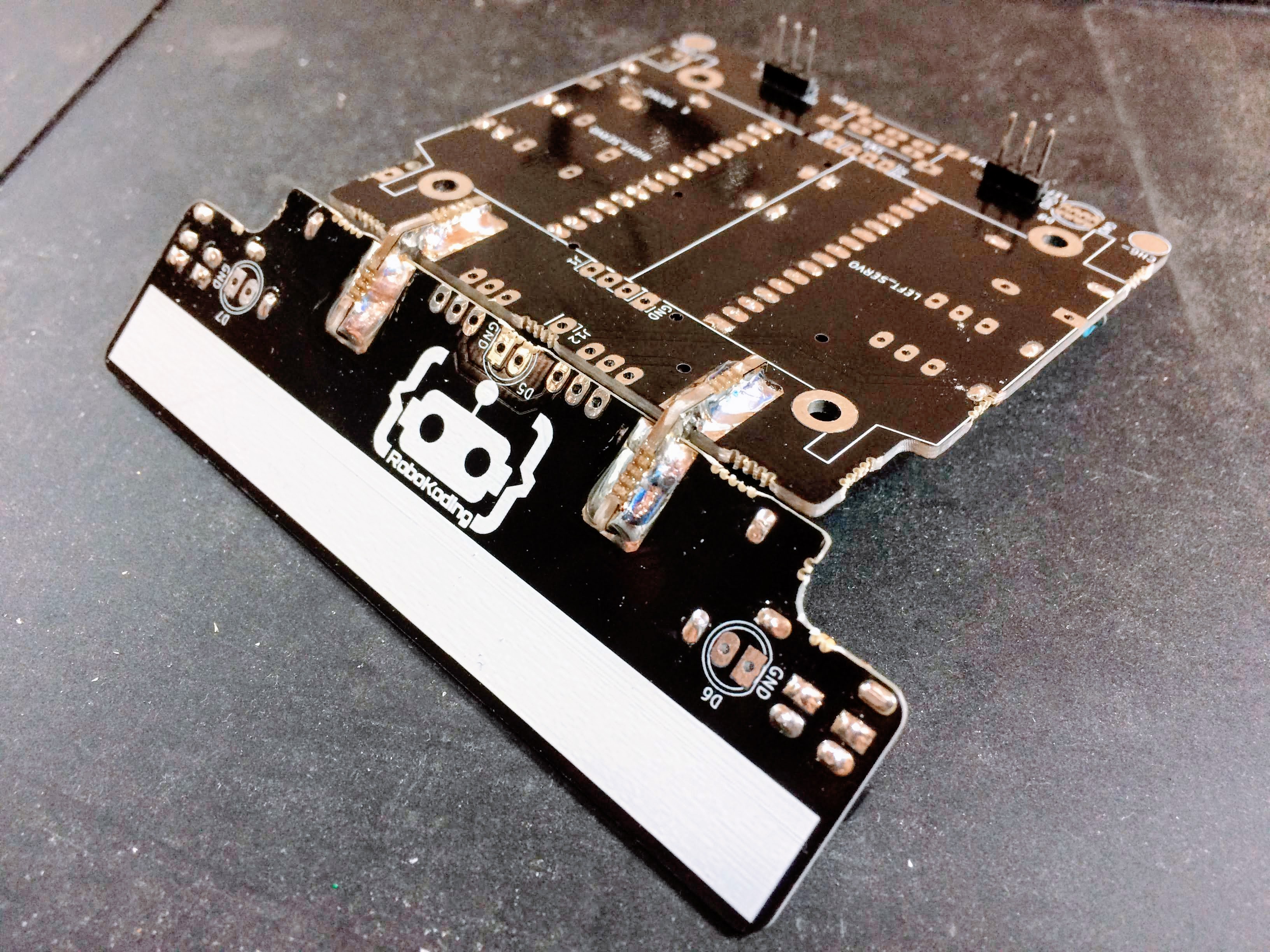
Then, take the remainders of the resistors’ legs from step 2. Place them in the holes on the board as shown on the image below. Solder them on both sides of the board, as well.
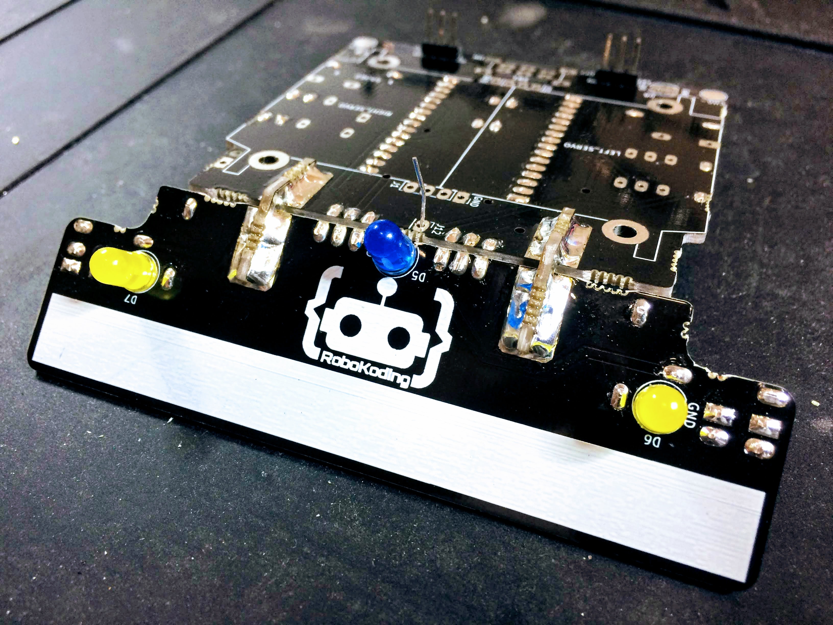
8. Solder the LEDs
Find the three LEDs - one blue and two yellow. Place the yellow ones in the holes with labels D6 and D7, while the blue one in the hole marked as D5. Be aware of the polarity again. Take a closer look and notice how the specific shape of the LED corresponds to the drawing on the board. You should place the shorter leg of the LED into the hole with a rectangular pad of the SumoBoard. After you make sure the polarity has the right orientation on the board, solder the yellow LEDs. The blue LED is placed in a more specific way. After you place the shorter leg in the hole marked with a rectangular shape, push the longer trough the J12 hole on the mainboard.
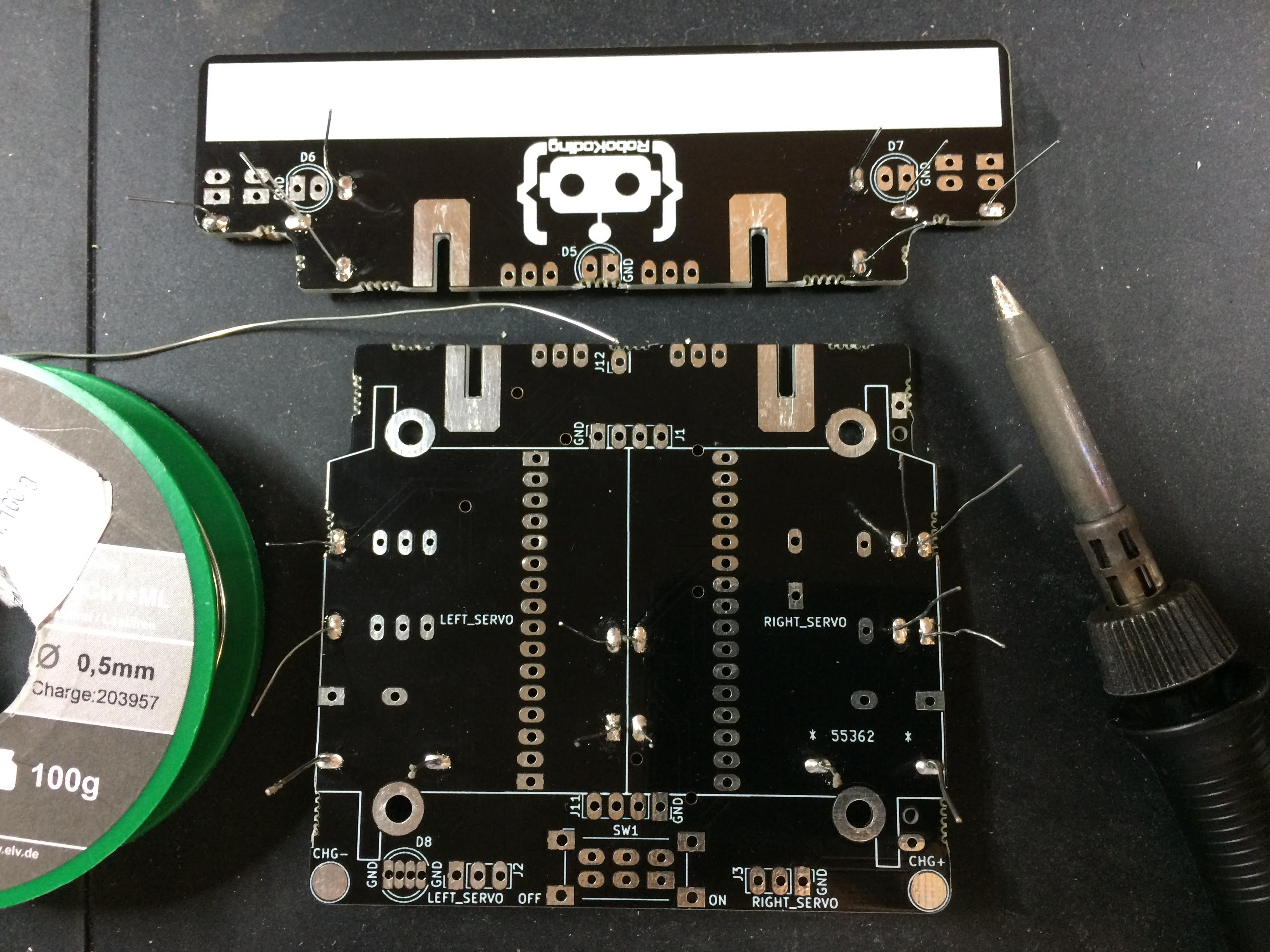
9. Solder the ultrasonic sensor
Find the ultrasonic sensor. This one helps the robot to detect objects, i.e. “to see” the opponent on the SumoRing. Push it in the holes labeles as J1 on the board and solder it into place.
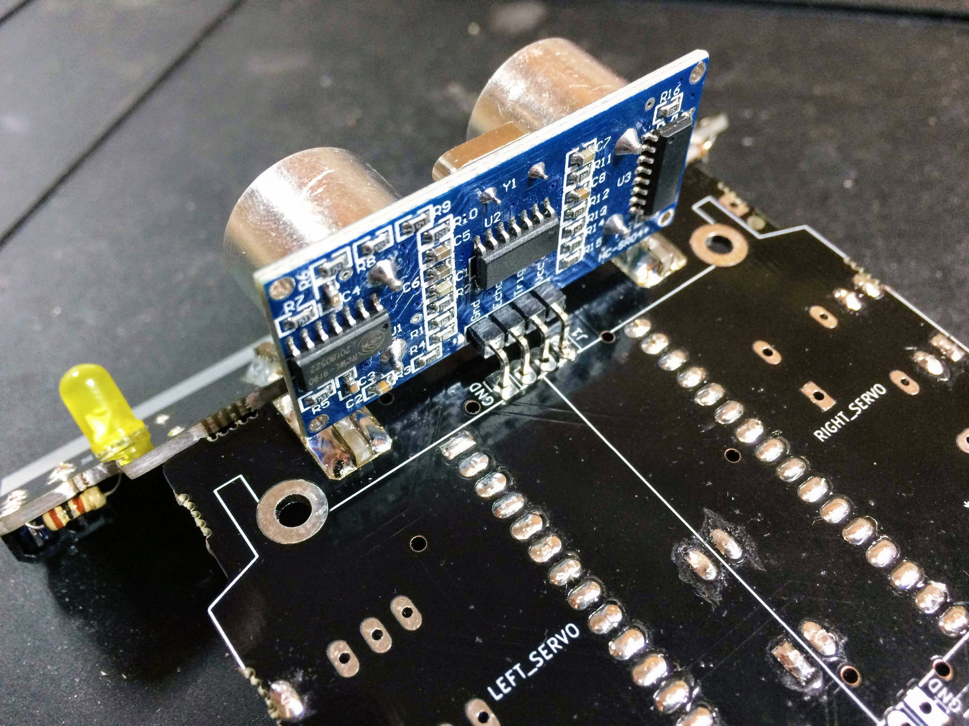
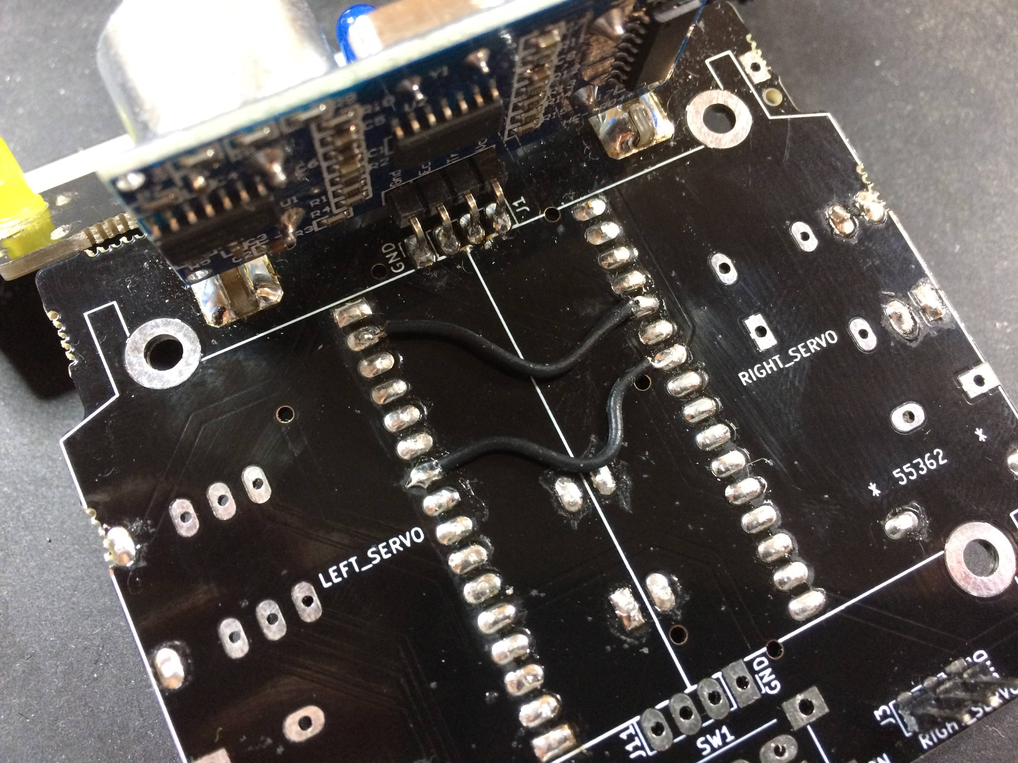
IMPORTANT! Do this only if you have the SumoBoard v0.3 not v0.3.1 or any later version. Solder 2 cables to connect the following pins.
10. Solder the power button
Put the power button in the SW1 labeled holes and solder it into place.
IMPORTANT! Do this only when you have the SumoBoard v0.3 not v0.3.1 or any later version. Add more solder to connect the lower right 2 pins together.
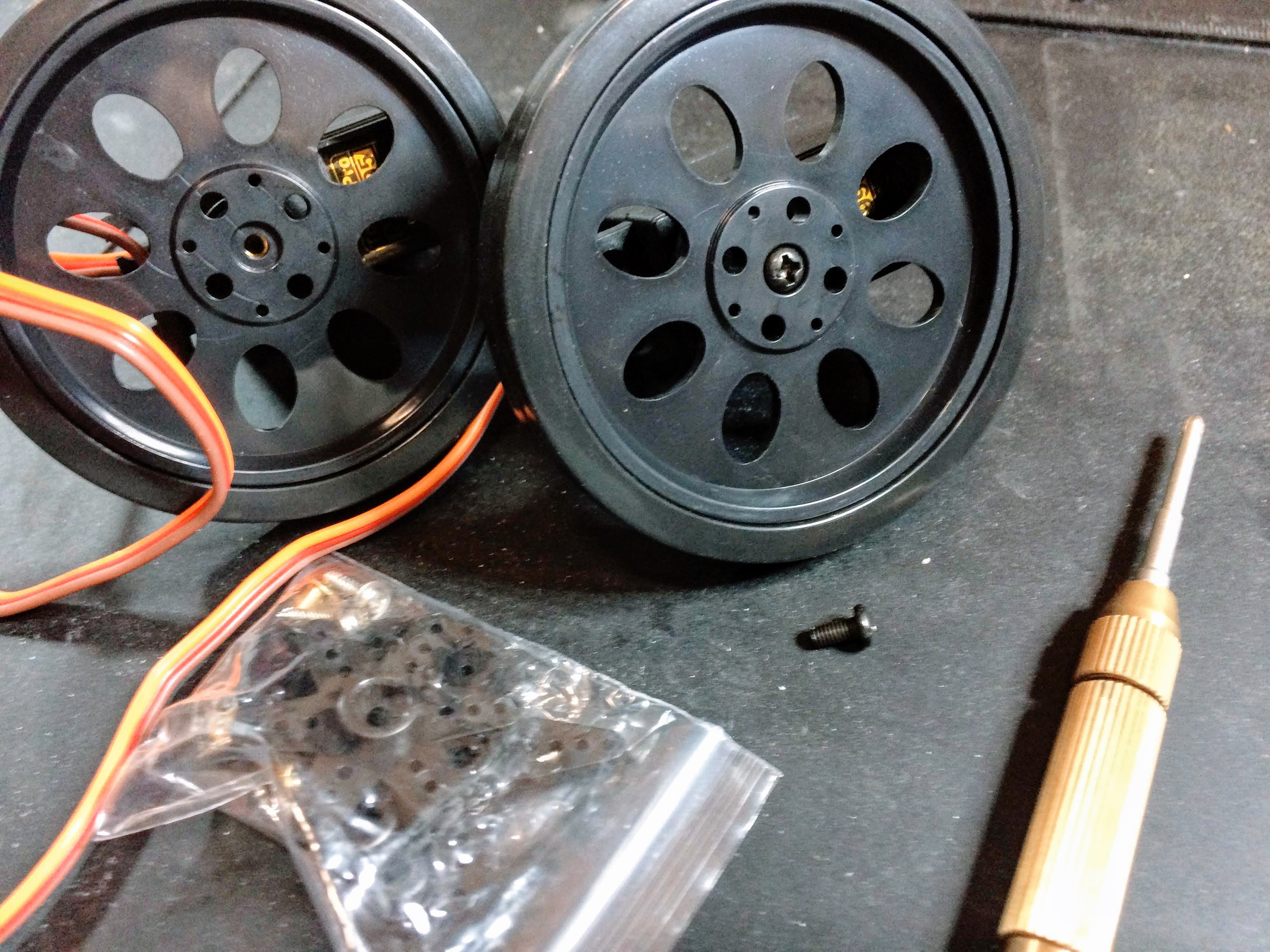
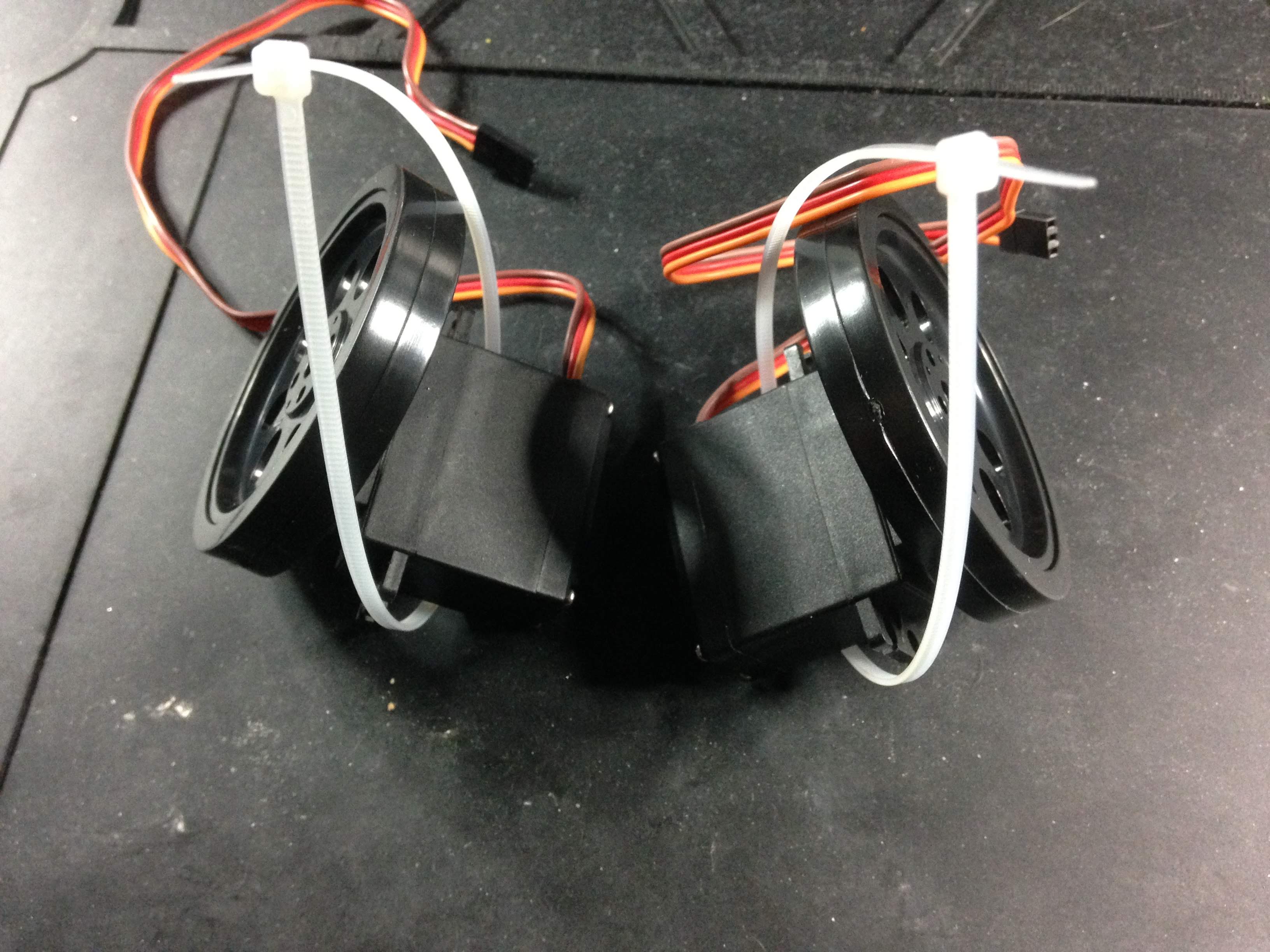
11.Prepare the wheels
The two wheels should be attached to the servomotors, so the robot can execute the movement commands. Find the two black screws from the bag and screw them to the wheels. Then place the zip ties around the servomotors.
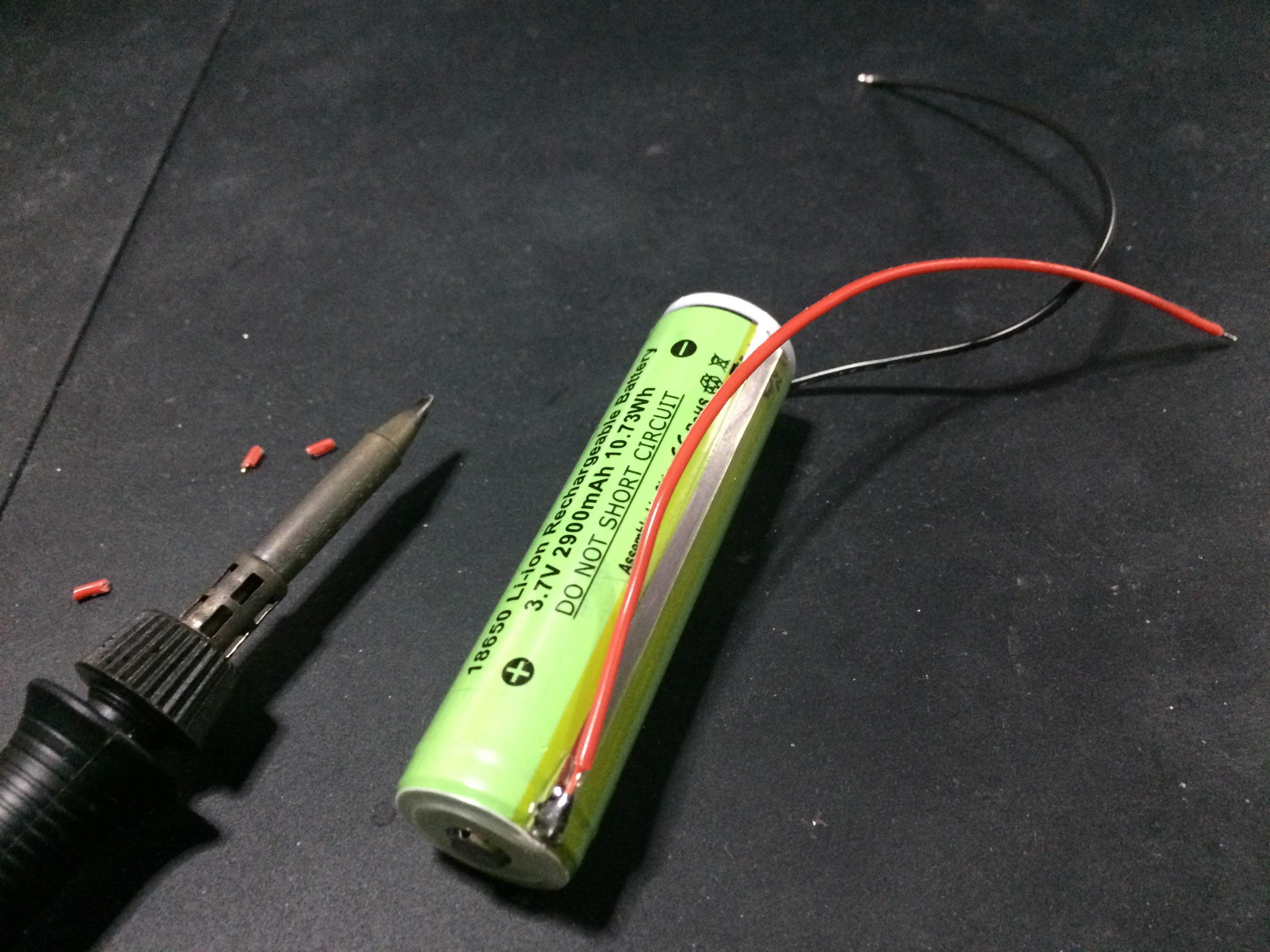
12. Connect the battery
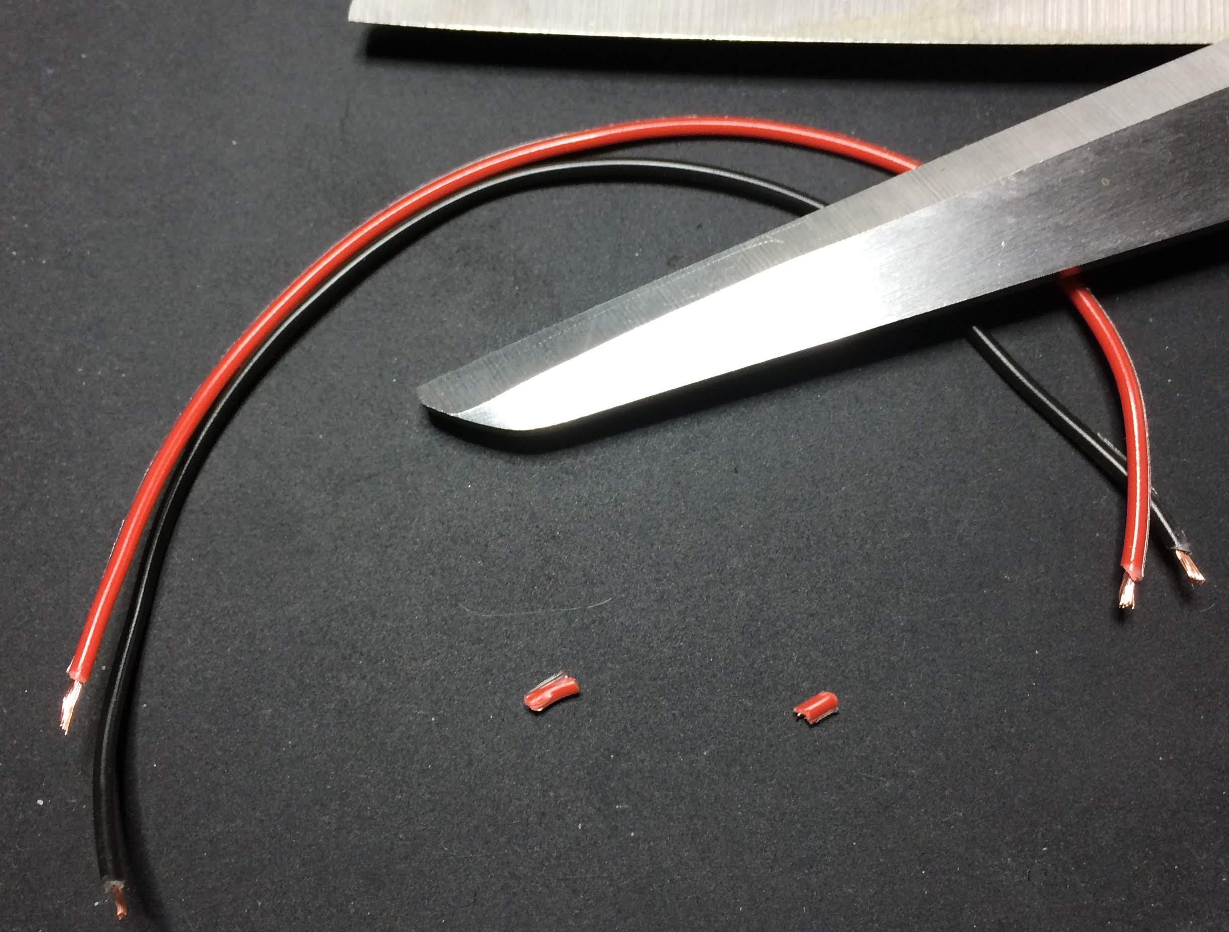
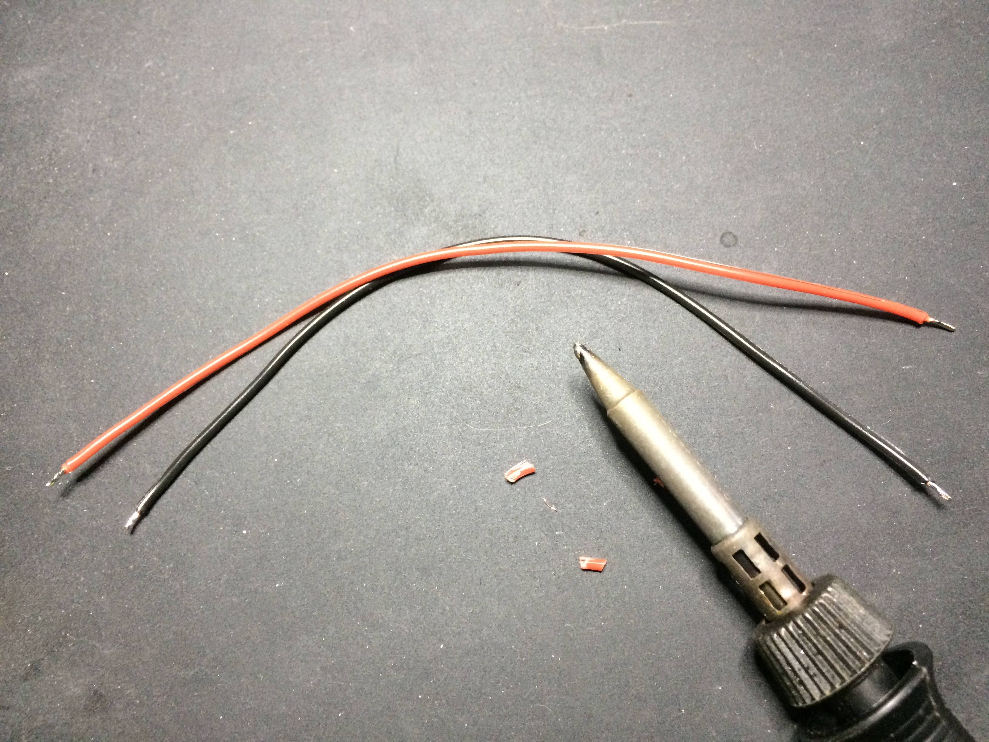
First, pull apart the black and red power cable. Then peal off some isolation from the cable ends with the pliers or edge cutters. Then Apply solder to the ends of the cables.
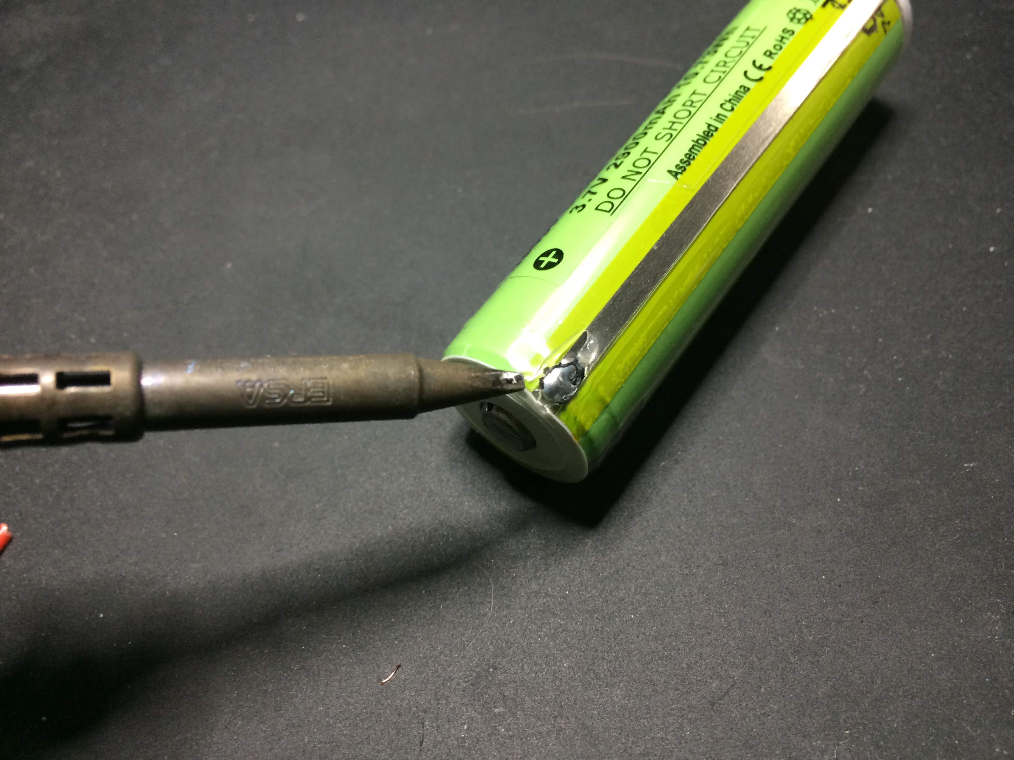
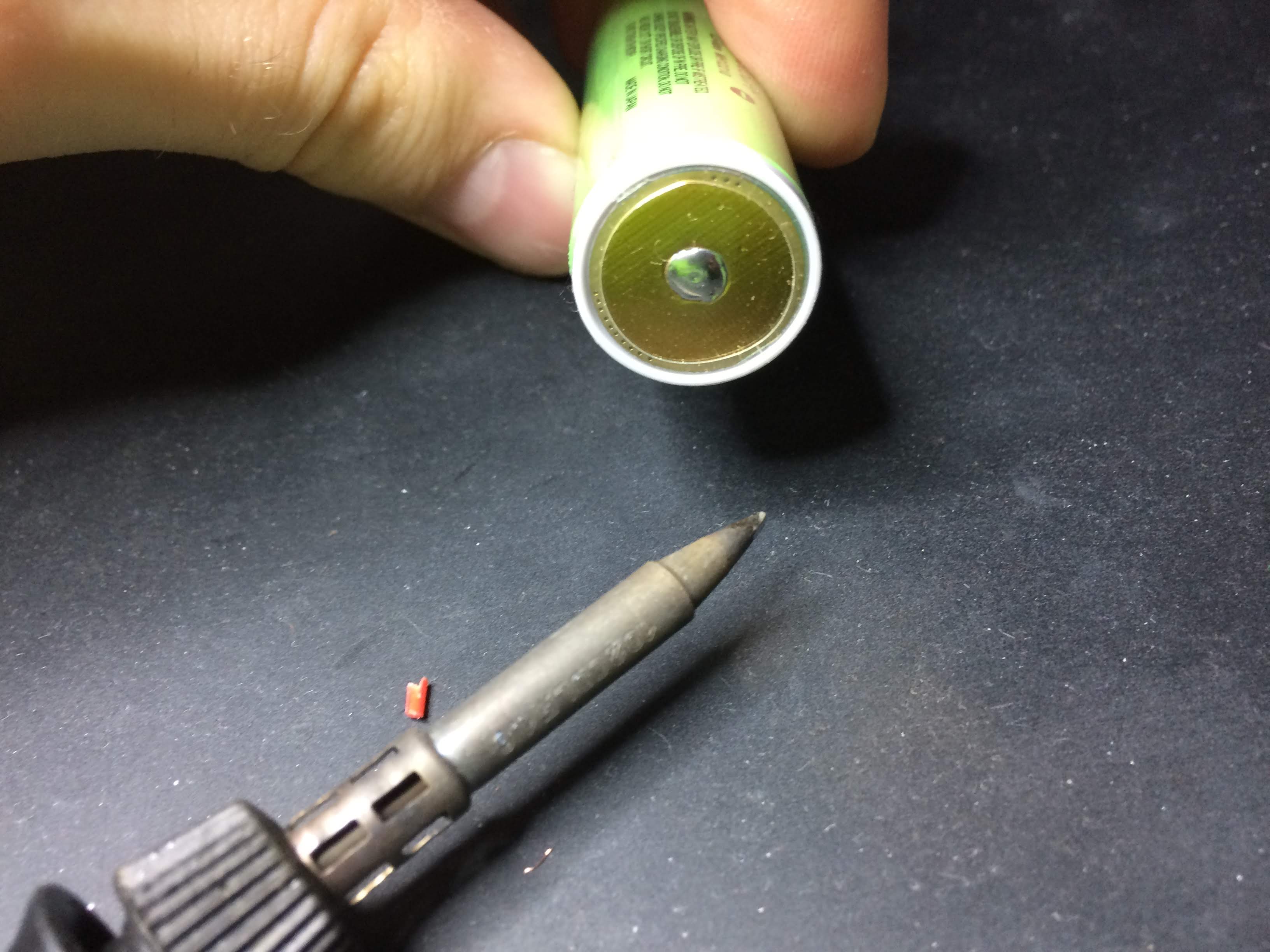
Next, apply some solder to the positive and negative pole on the battery. To apply solder on the positive end of the battery you need to burn off the isolation a bit. Keep in mind that heating up the battery too much is not good, so it’s best to do the soldering quickly.
After that, solder the cables to the positive and nagative side of the battery.
Finally solder the battery to the SumoBoard, red cable to BAT+ (J6) and black cable to BAT- (J7). You can either solder them directly to or connect them trough the assistive holes by making a small loop, like shown on the images below.
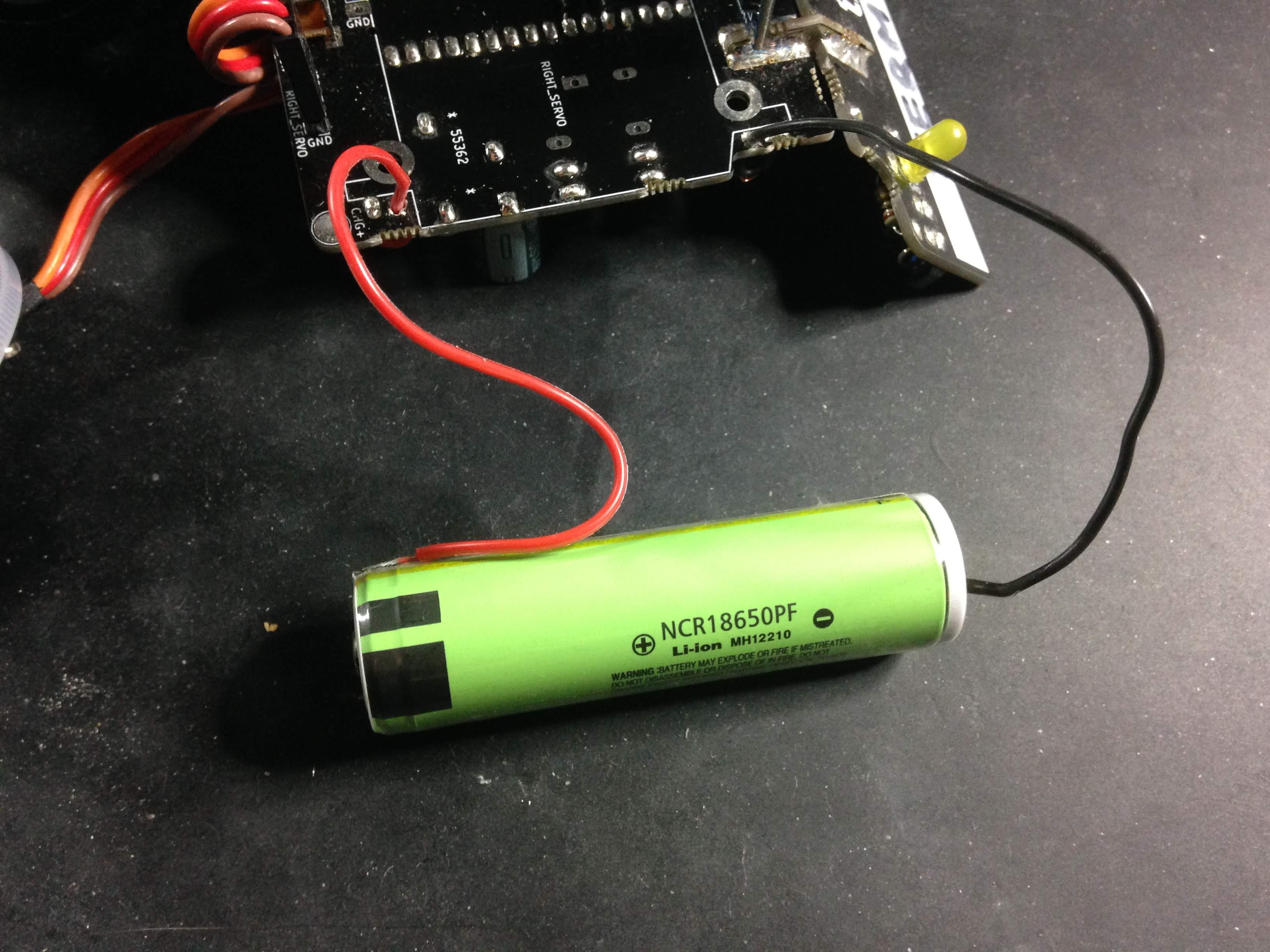
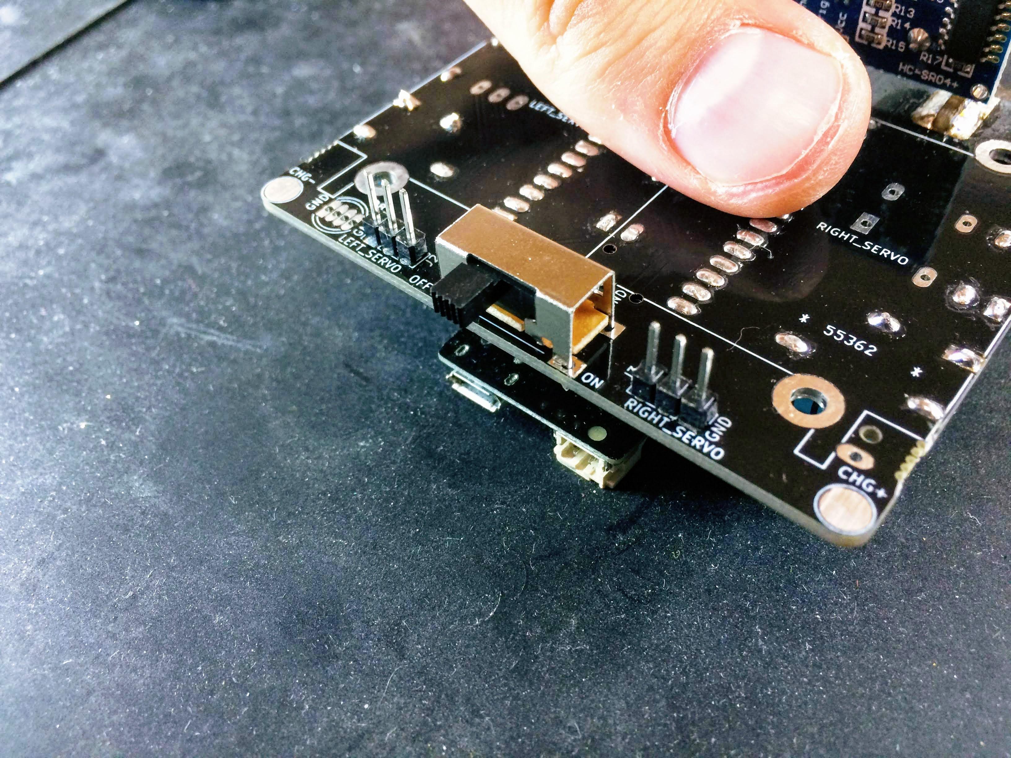
TIP: Be careful that the power button SW1, which was soldered earlier, is turned OFF. The slide switch should be on the left, OFF position.
13. Fasten the servomotors and the battery
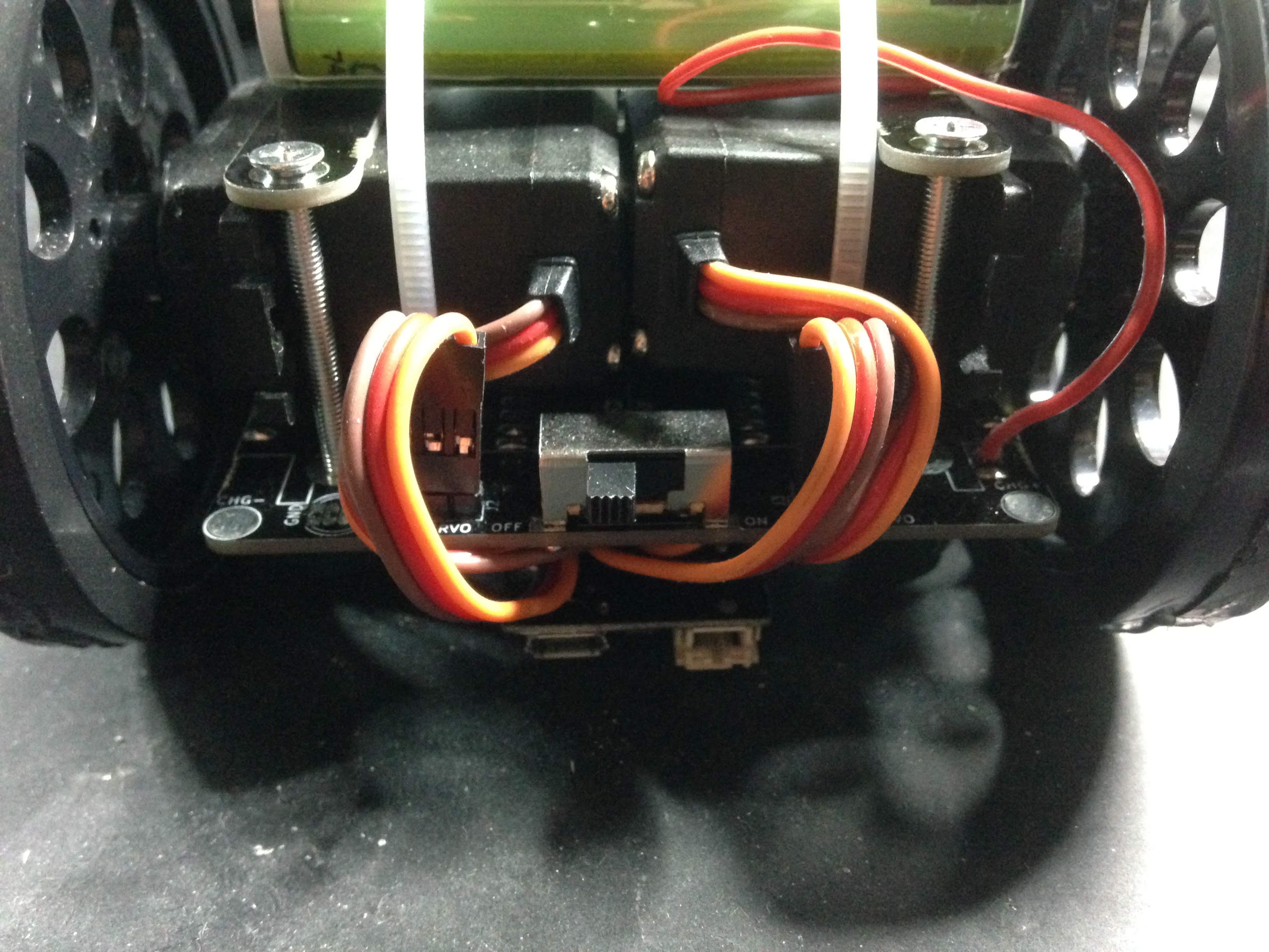
Place the servomotors on the SumoBoard with the zip ties around them, on top of the labels LEFT_SERVO and RIGHT_SERVO. The positioning is important - the servomotors cables should go towards the back of the robot, where the power switch is. Afterwards, place the black breakaway tabs on top of the servos (the narrow stick with two screw holes) from the first step. Then place the battery trough the zip ties, on top of the servomotors. Pull tight the zip ties and cut the remainders.
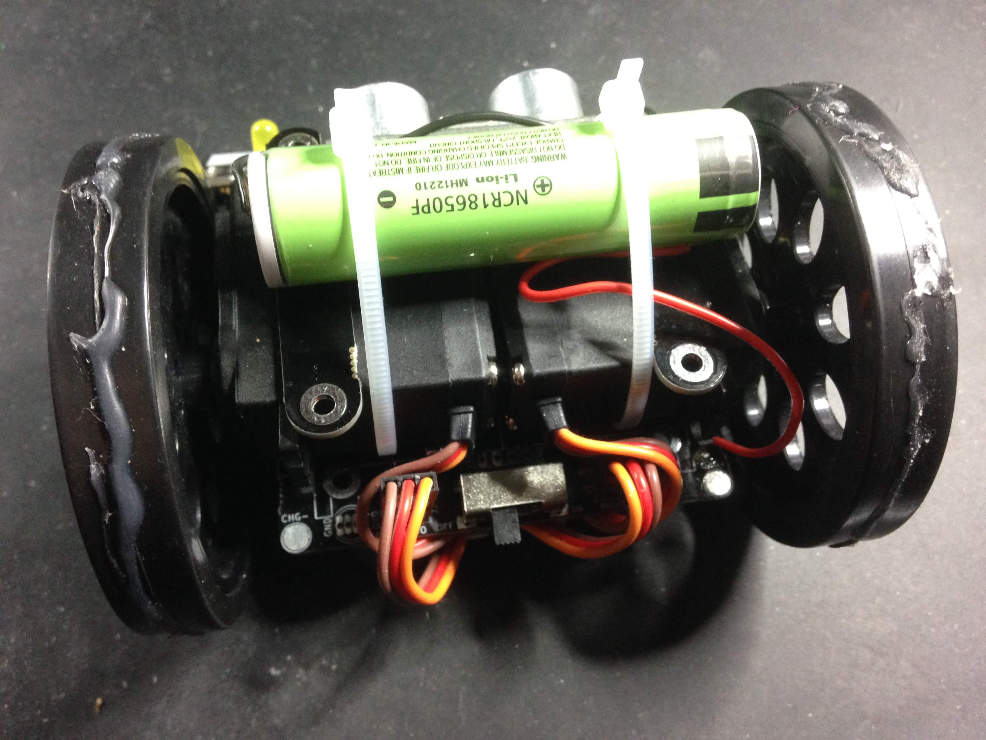
Insert the screws from up, the nuts from below and then screw them together. When this is done, you can put the cables under the microcontroller, as shown in the pictures below.
TIP: You can add some hot glue or other means to make the wheel have more friction.
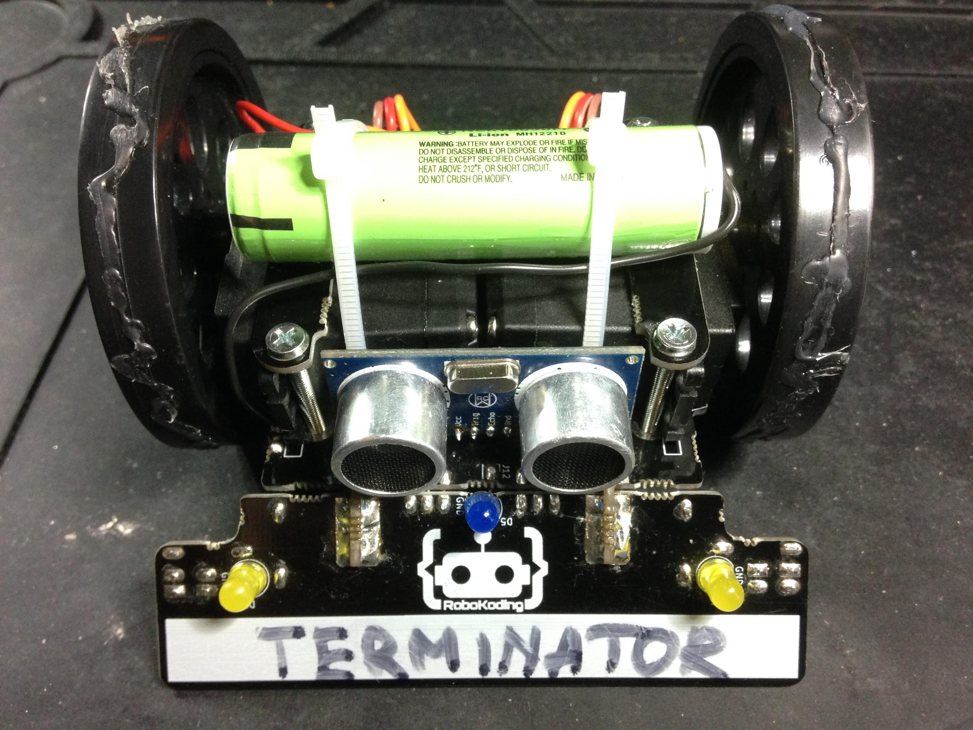
Finally add a name on your SumoRobot and your done with assembling it!
Usage instructions
To turn ON the SumoRobot slide the big power switch to the right (ON). To turn the SumoRobot OFF, slide the big power switch to the left (OFF).
In order to charge the SumoRobot, plug the micro USB into the SumoRobot’s microcontroller. The red charging LED will light up. The SumoRobot can be charged in both ON and OFF state. Once the battery is full the red LED light will turn OFF.
Connecting to WiFi is possible using the SumoManager app. Keep in mind to use the SumoManager, the SumoRobot has to be turned ON. The blue LED under the SumoRobot will blink when it’s trying to connect to the WiFi network. Once connected to WiFi the blue LED will be steady ON.
The yellow LED lights indicate if the SumoRobot is seeing a line. This works only on the SumoField or on a white paper with a thick black line. There are two line sensors under the plow of the SumoRobot, on the left and right. You can print your own SumoField on a A0 paper at a local print shop, download it here.
The blue LED light indicates if the SumoRobot sees something in front of it. It sees about 40cm in distance.
Debugging problems
In case you are facing some problems with the SumoRobot you can contact letstalk@robokoding.com In case you are interested to debug problems yourself you can head over to GitHub to find all the design files and software.