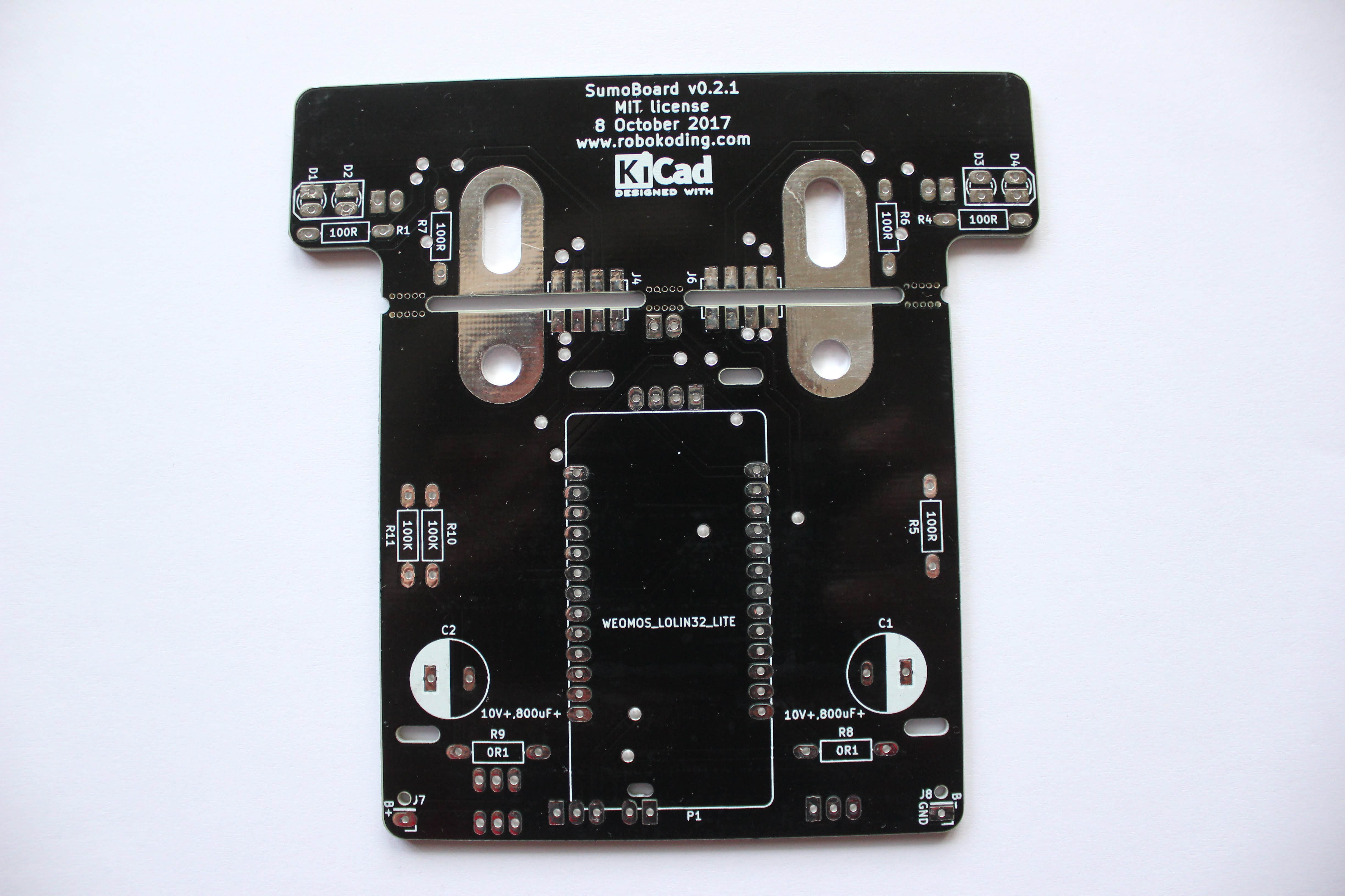
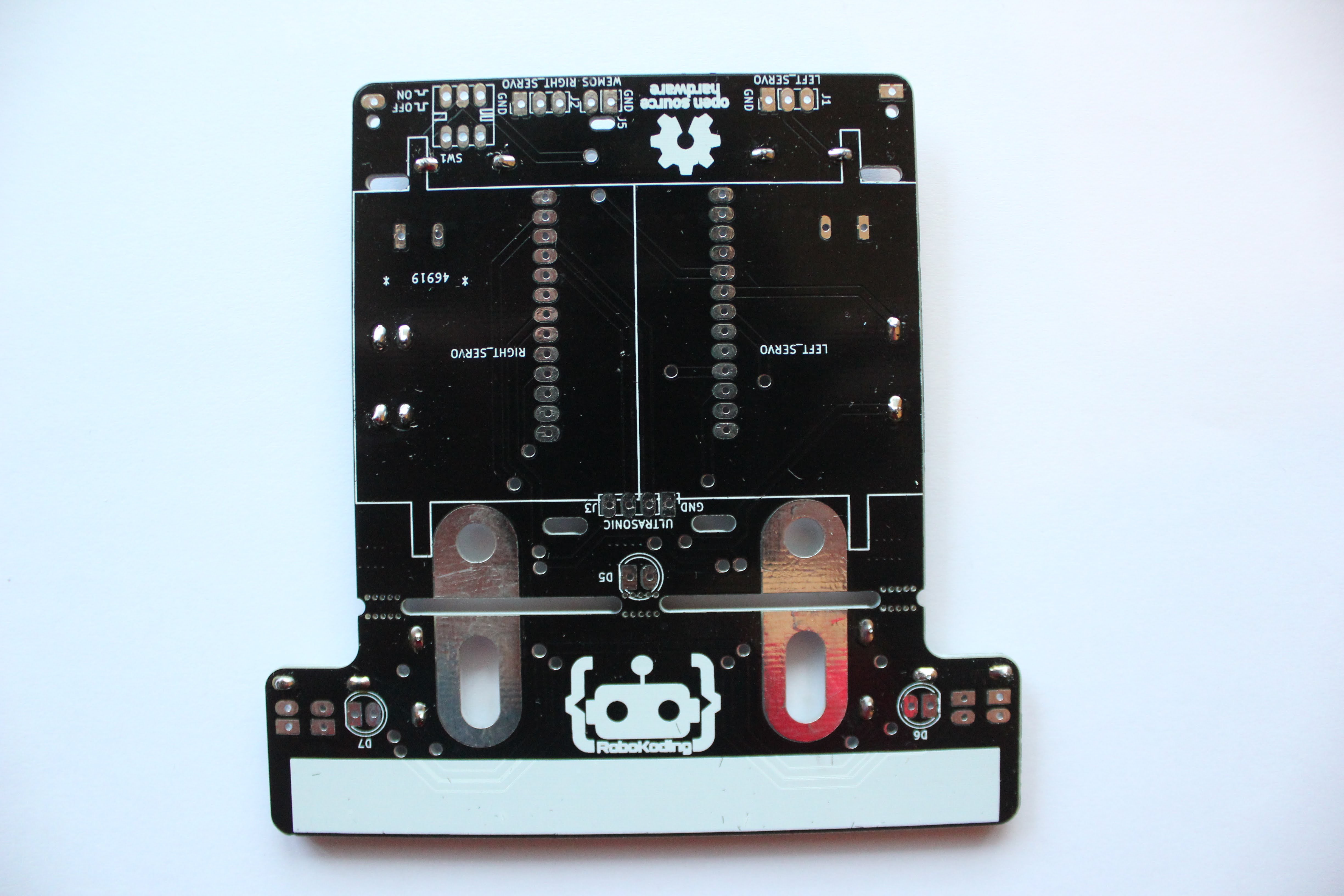
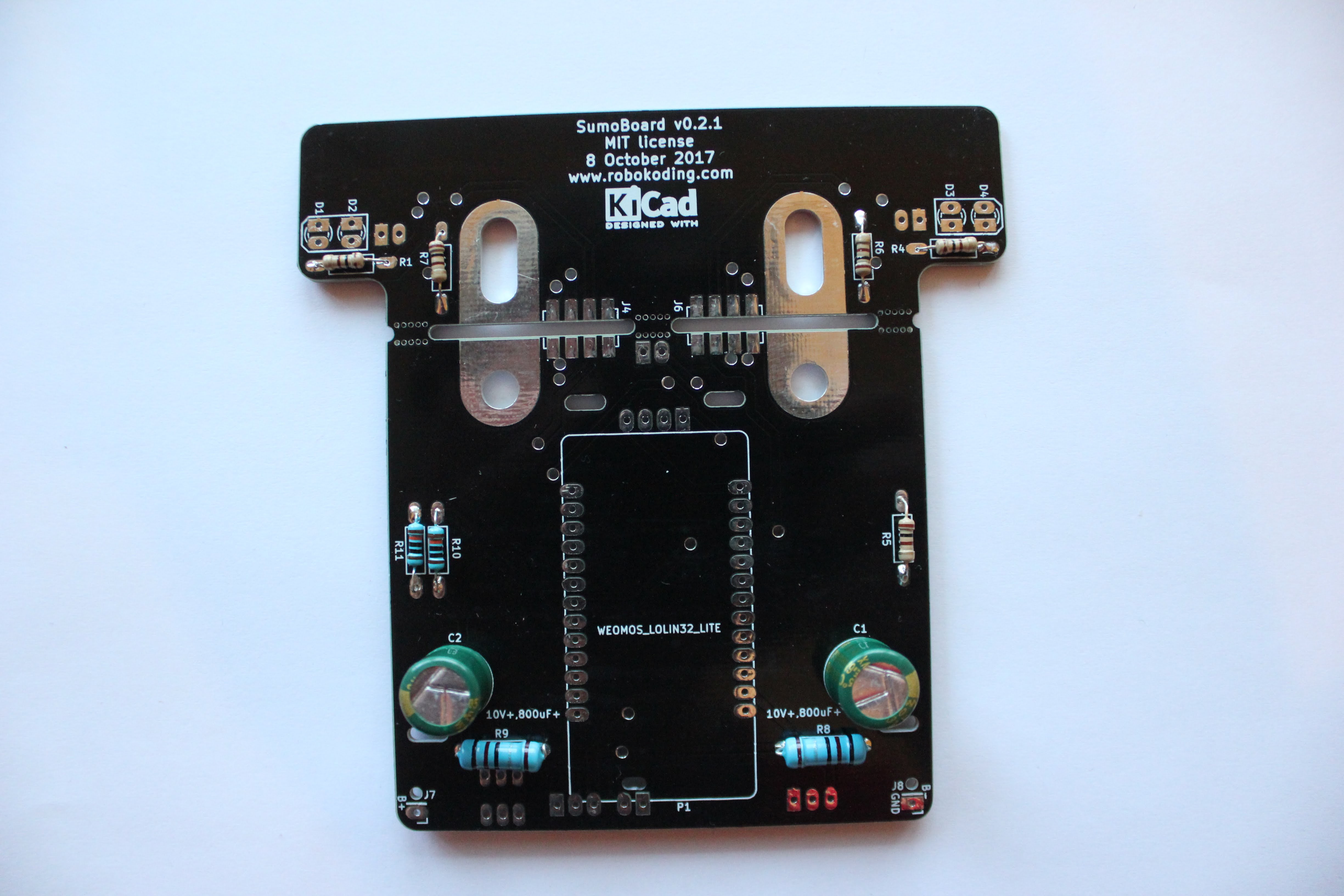
SumoHardware v0.2.X
Assembly instructions
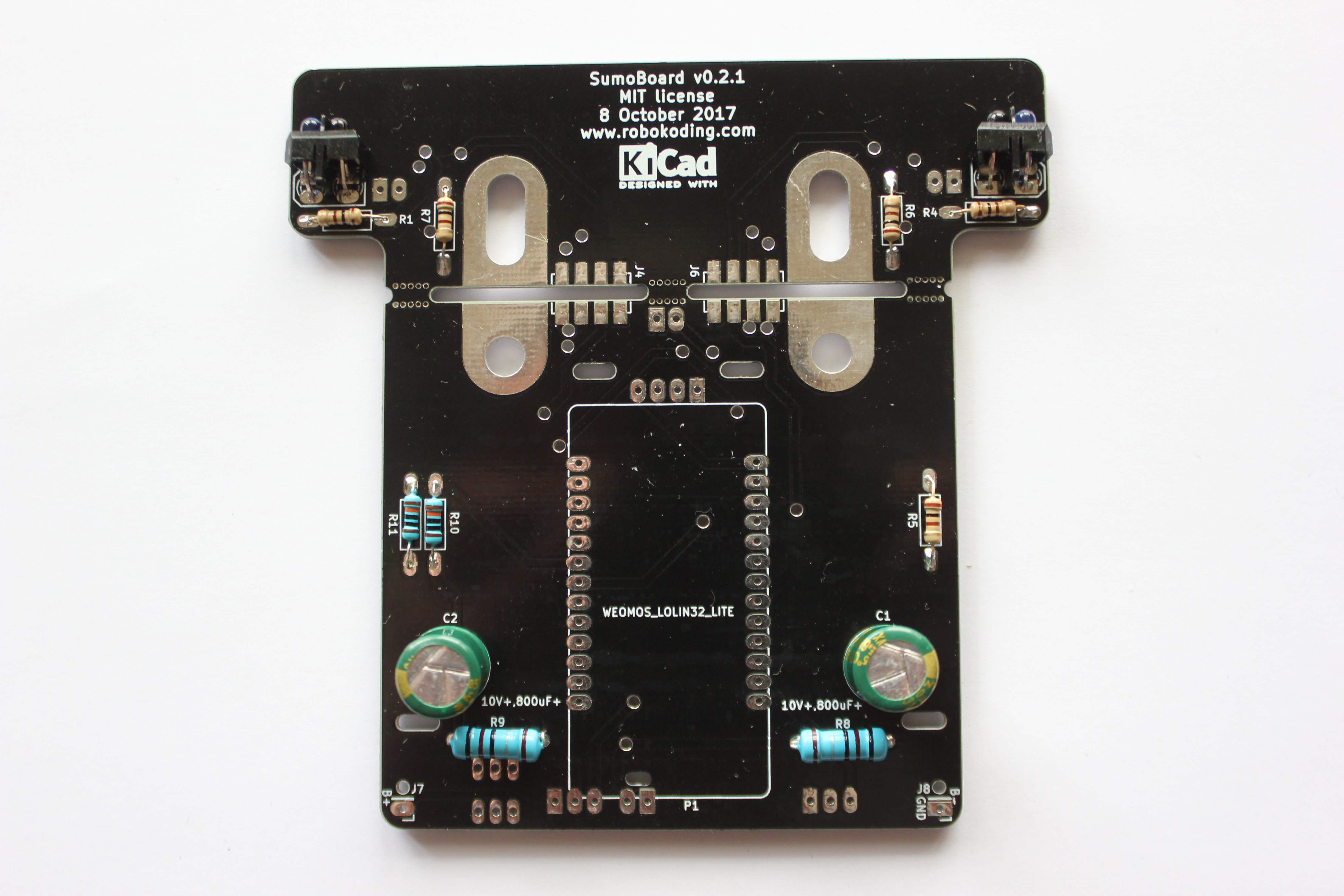
1. Solder the resistors
Flip the SumoBoard on it’s backside.
R8, R9 = 0.1 ohm (big blue resistors)
R10, R11 = 100K ohm (small blue resistors)
R1, R4, R5, R6, R7, = 100 ohm (small light grey resistors)
It is probably easiest to place the resistors and solder them one by one. Bend the resistor legs 90 degrees and place them trough the SumoBoard. The resistors don’t have polarity, you can place them any way you want. The holes for the big blue resistors are a bit too close together.
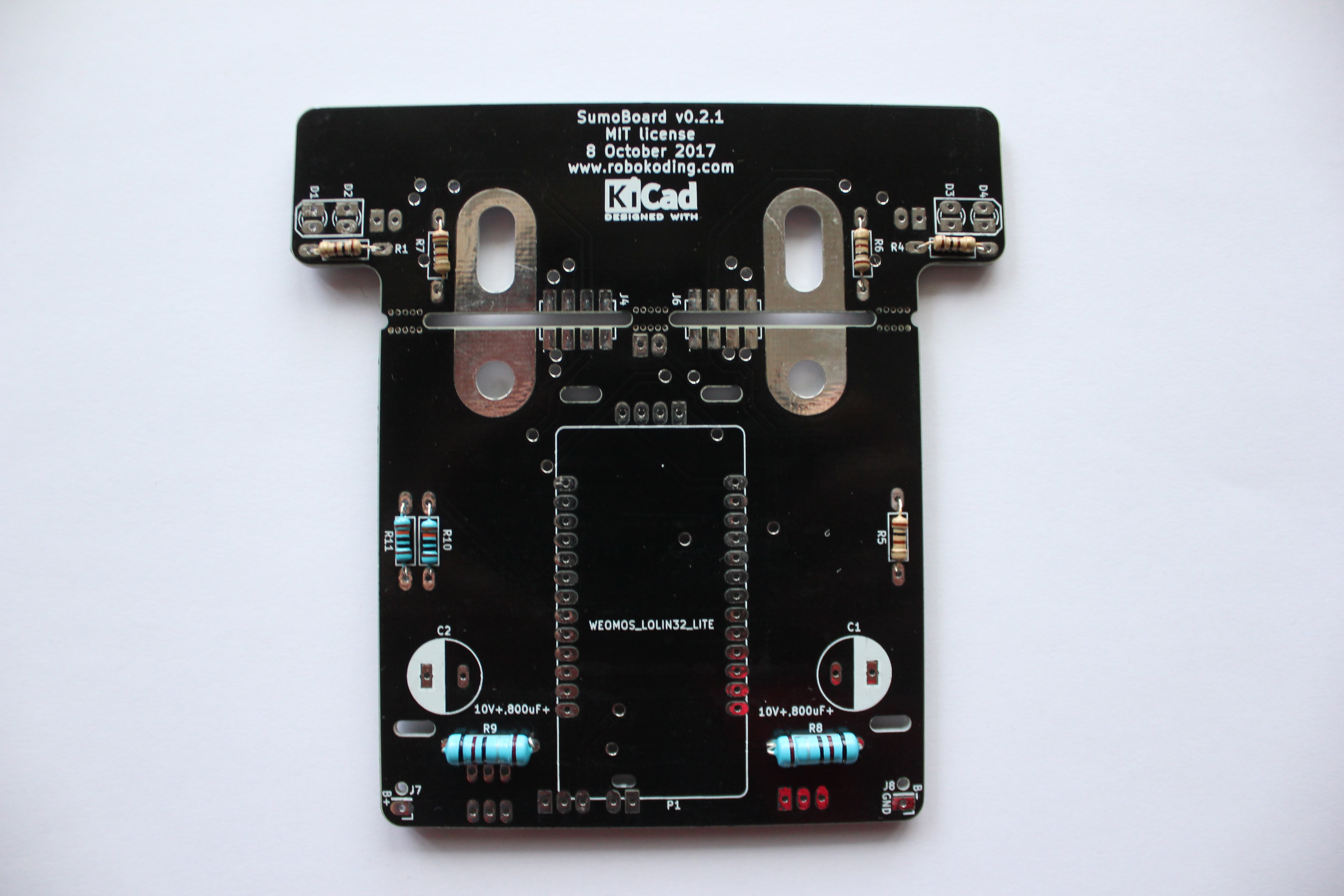
Once the resistor(s) is(are) in place, try to hold it in place with your finger (or keep the SumoBoard pushed against the table) and turn the SumoBoard around to solder the resistor from the other side and cut the remainder of the resistor legs.
TIP: It’s best to use some of the cut resistor legs and solder them to the solder jumpers for the plow. It will make the SumoRobot more durable in the end. Just solder them from one side, the other side will be soldered in a coming step.
TIP: For best soldering results preheat the resistor leg and the pad with the tip of the soldering iron few seconds before and then apply solder wire. Add enough solder wire to make a mountain around the resistor leg and then remove the solder wire and leave the solder iron tip for few seconds on the pad. Then remove the solder iron and you should have a nice shiny solder connection.
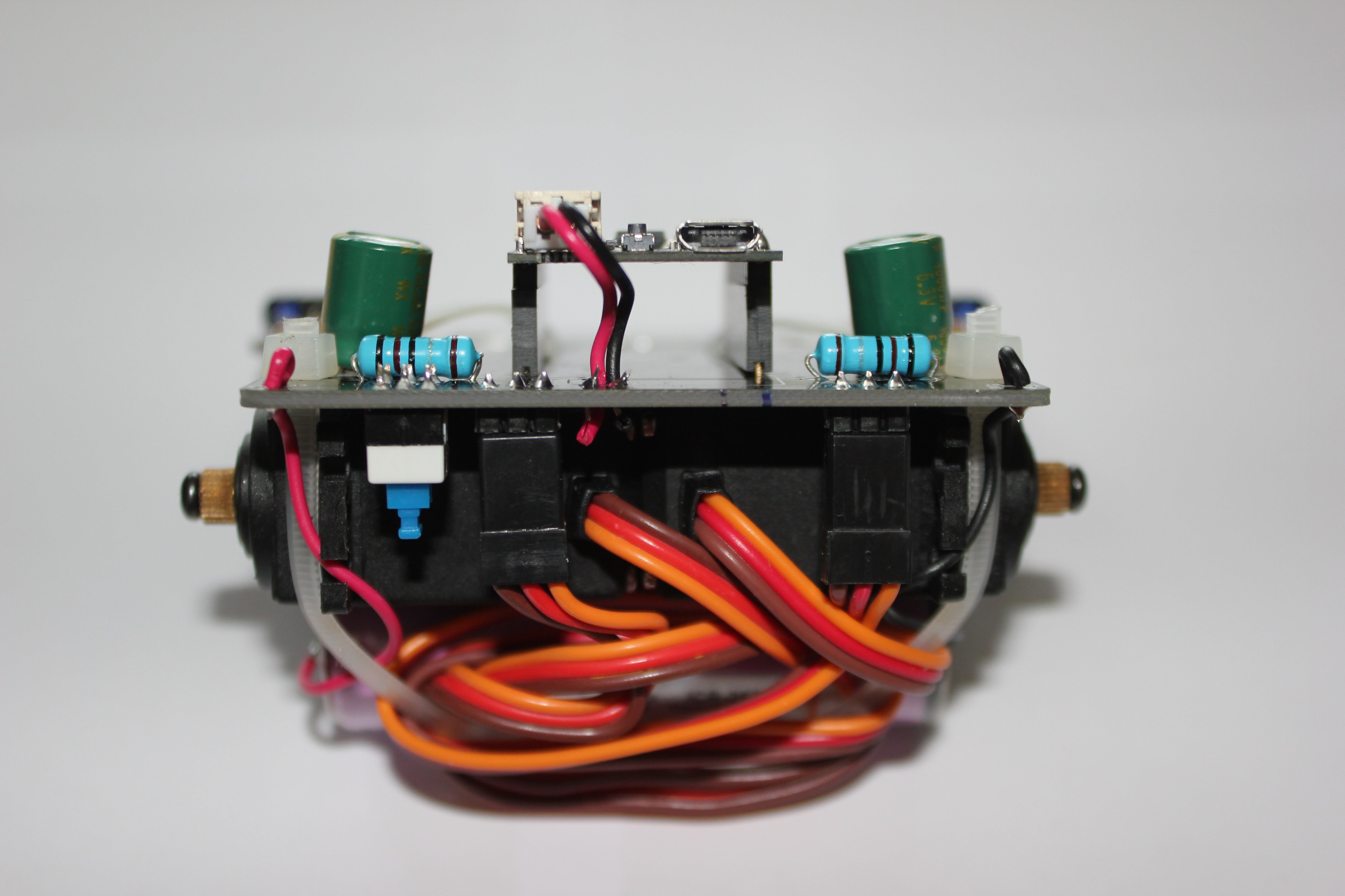
2. Solder the capacitors
The 2 green cylinders are the capacitors. On one side of the capacitor body there is a yellow/brown side with stripes. The capacitor leg with the striped side goes into the SumoBoard hole which is surrounded by a white half circle under the C1 and C2 labels. Try to leave some space between the SumoBoard and the capacitor. So that the capacitor doesn’t touch the SumoBoard. This makes one of the next steps easier. See images below for 2 options how to place the capacitors.
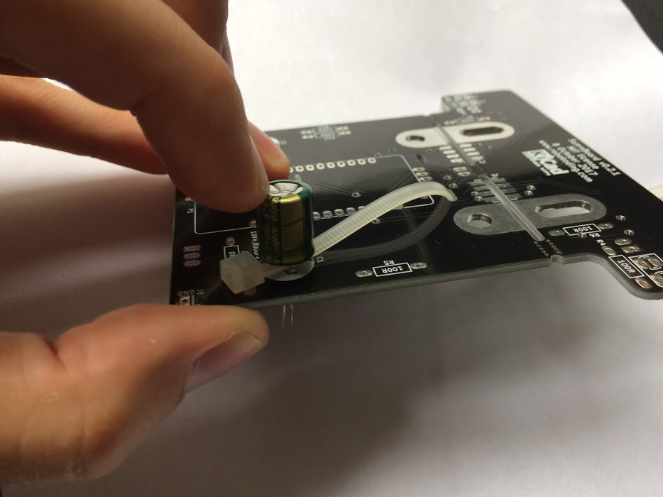
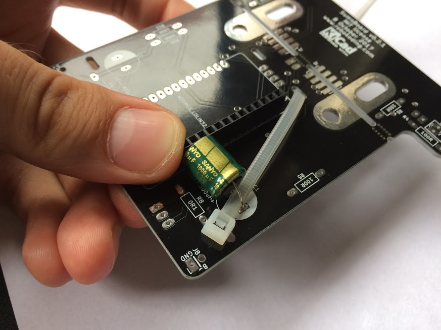
Finally however you placed the capacitors, now remove the zip ties.
3. Solder the line sensors
The line sensors are the dark blue LED and black phototransistor combined with the black chassis. Here again the polarity is important, so mind the white drawing on the SumoBoard to see which way they go to the holes of D1, D2, D3, D4. The cut corners of the phototransistor black case go towards the edge of the SumoBoard, so that the dark blue LED is closer to the edge of the SumoBoard. When you have figured out which way they go then you have to bend the legs 90 degrees. Like seen on the image below.
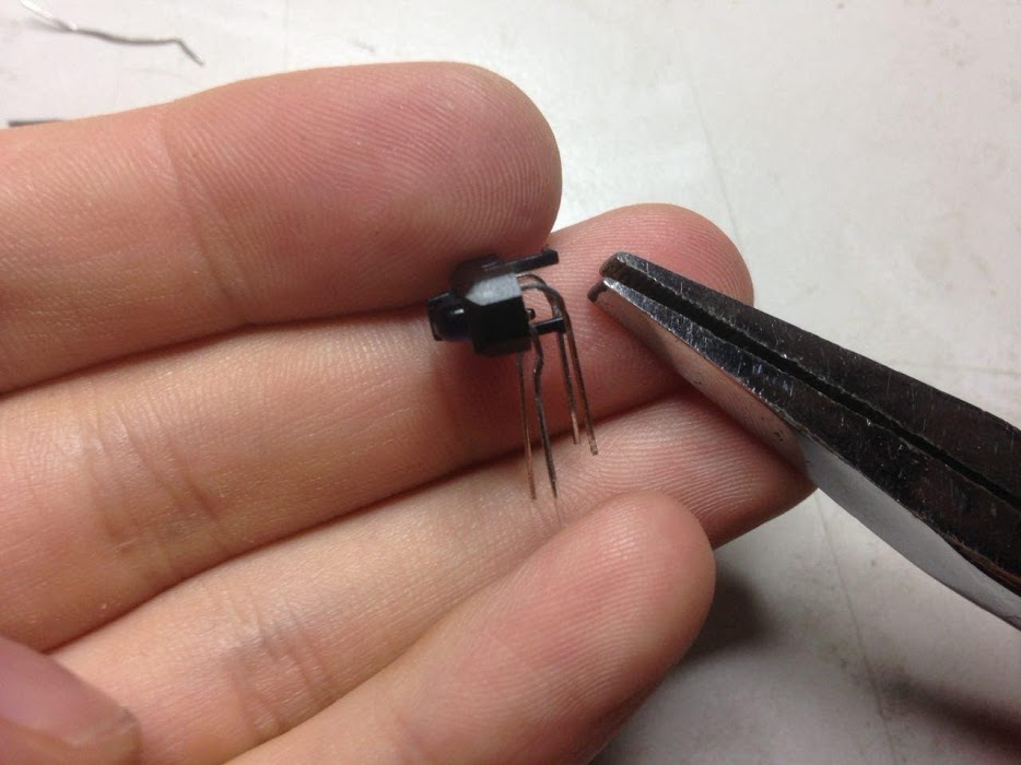
Finally place and solder the phototransistors one by one.
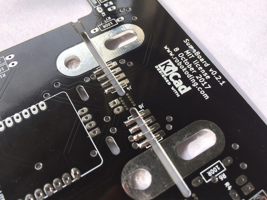
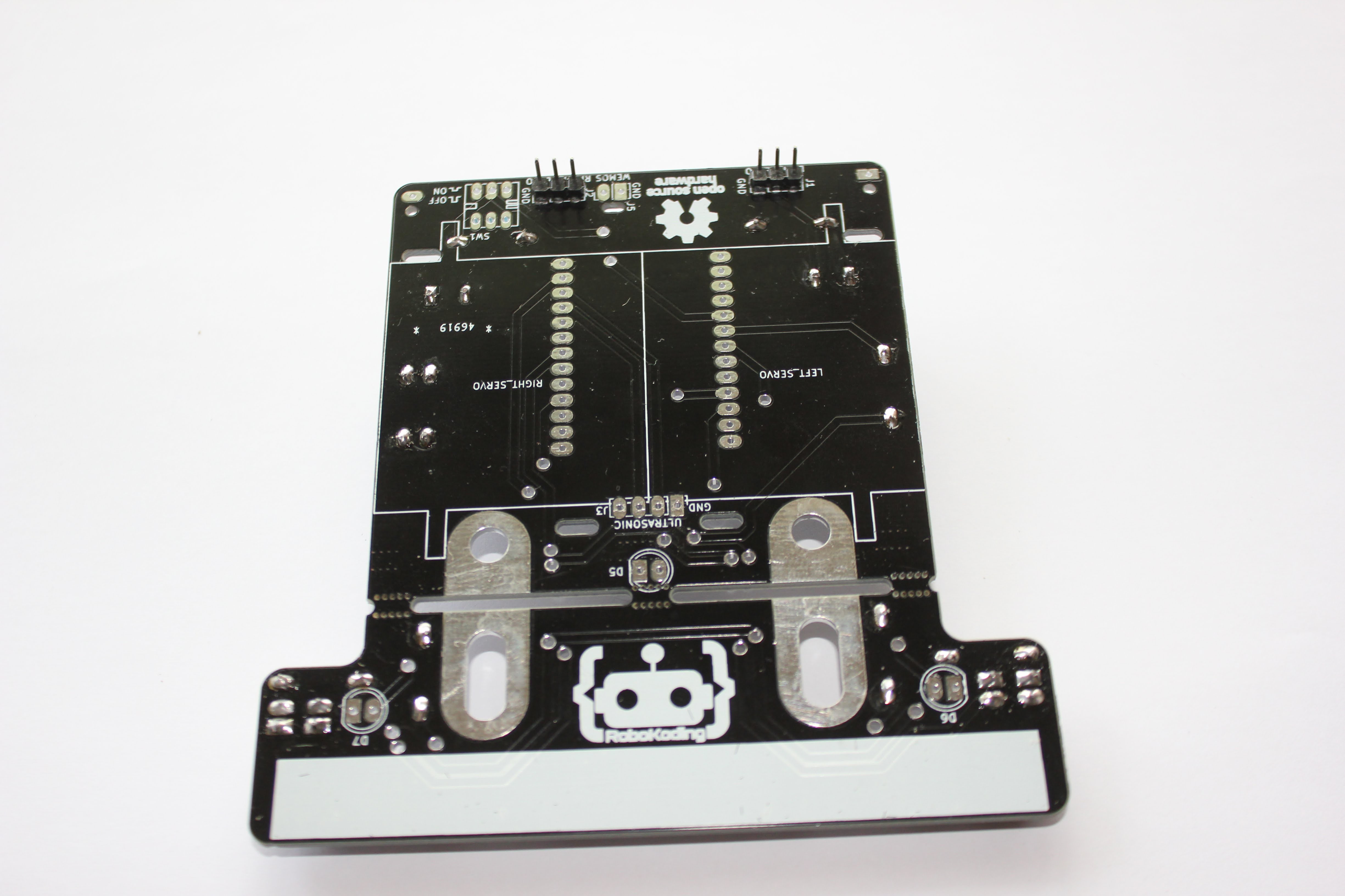
4. Solder the Servo pin headers
The 2 pin headers for the Servos go to the holes with labels LEFT_SERVO and RIGHT_SERVO. Place the pin header and solder one of it’s pins first. Then try to align the pin header while reheating the previously made solder connection.
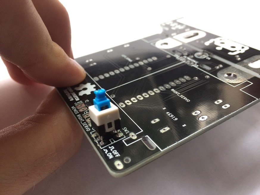
5. Solder the push button
Put the push button in the SW1 labeled holes. The polarity is important again, check the sides of the button, they should match with the drawing on the SumoBoard. There are 2 rectangles and a single rectangle drawn on the SumoBoard, they should match with the ones on the push button. See the images below.
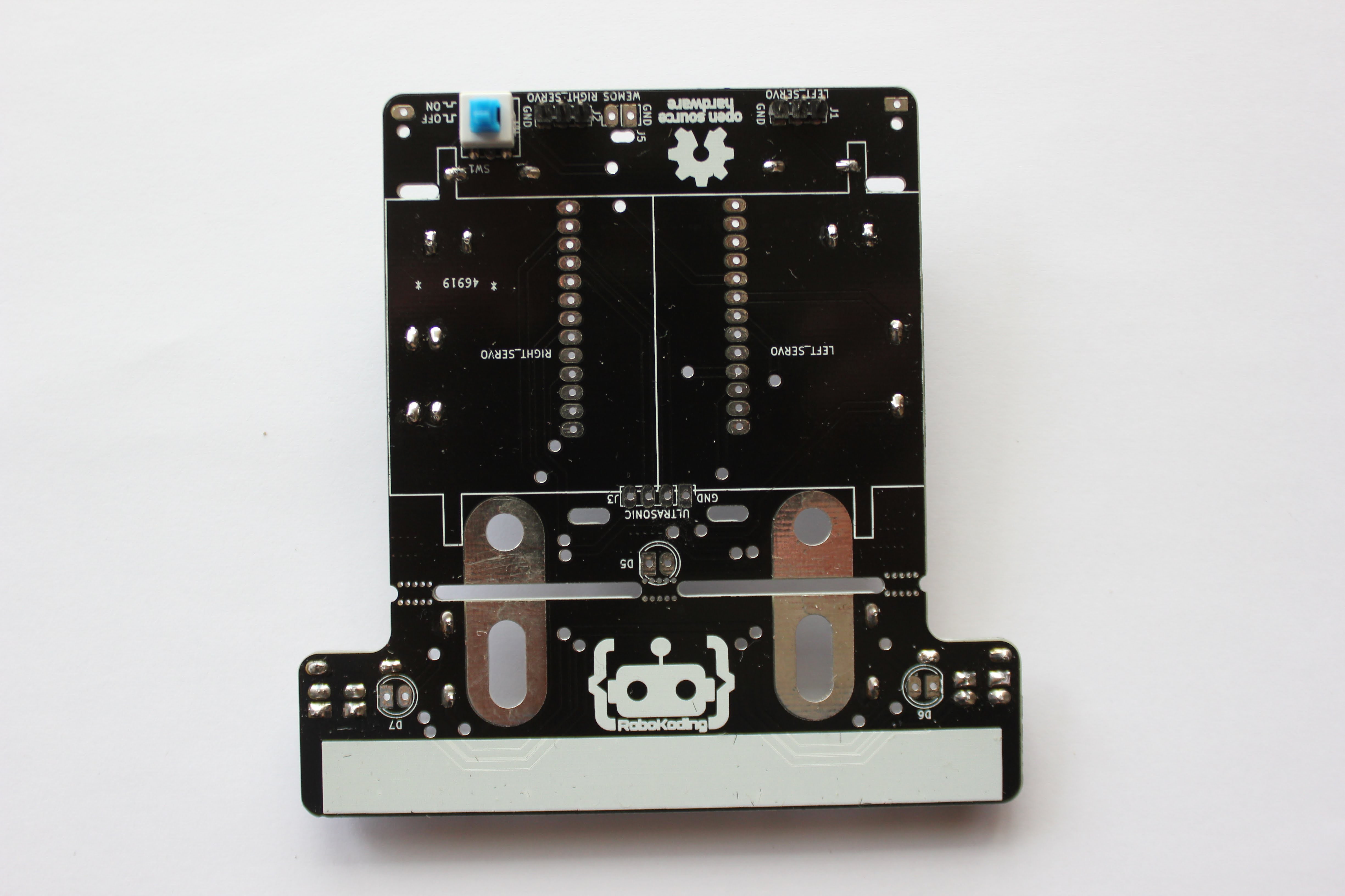
6. Solder the LEDs
The D5 is the blue LED and D6 and D7 are yellow. Be aware of the polarity again. One side of the LED is cut a bit like marked on the SumoBoard. The shorter leg of the LED goes into the hole with a rectangular pad of the SumoBoard.
7. Solder the microcontroller
Put the 13 pins long male pin headers into the microcontroller and also connect the 13 pin long sockets to it. Then solder the pin header to the microcontroller and the socket to the SumoBoard.
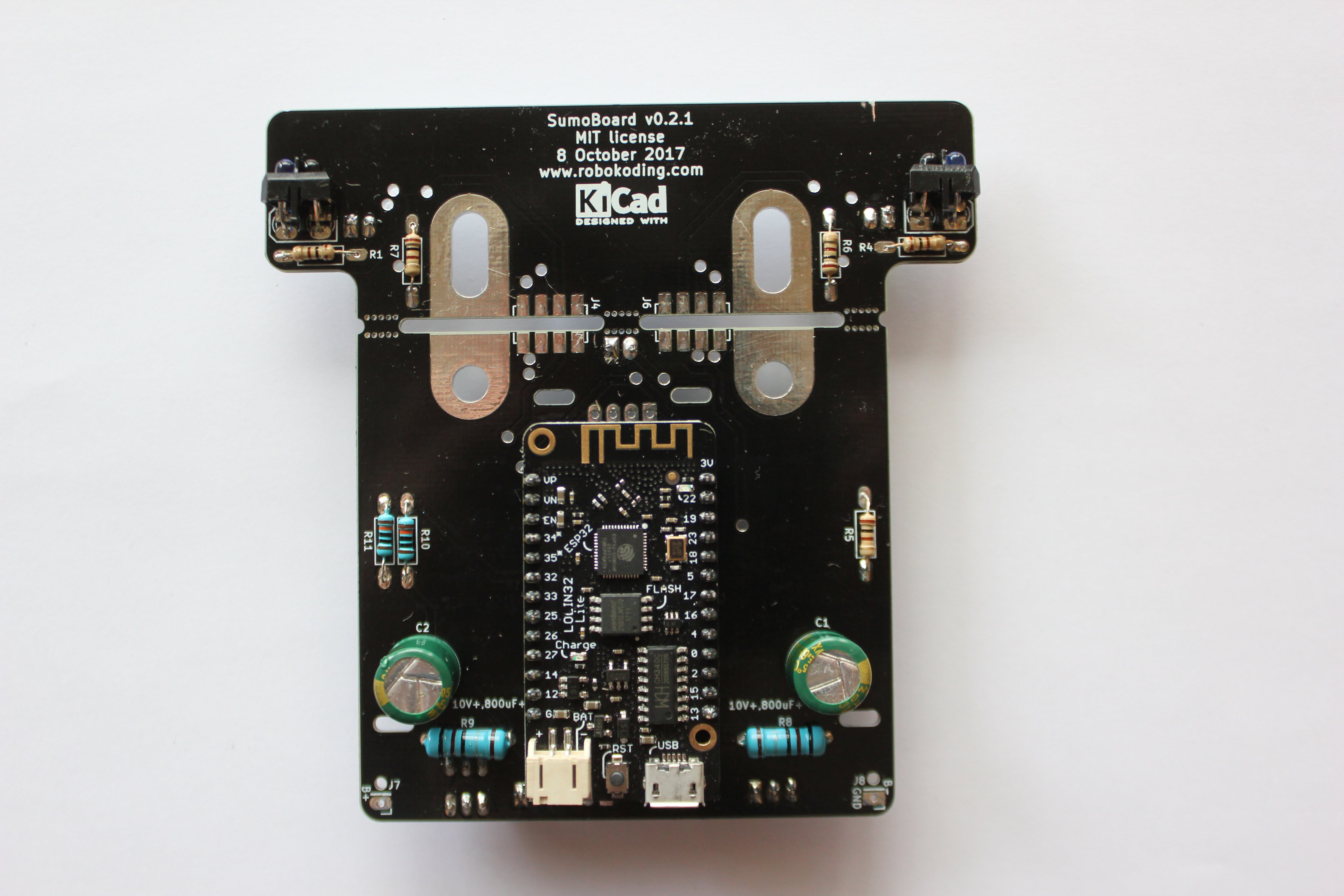
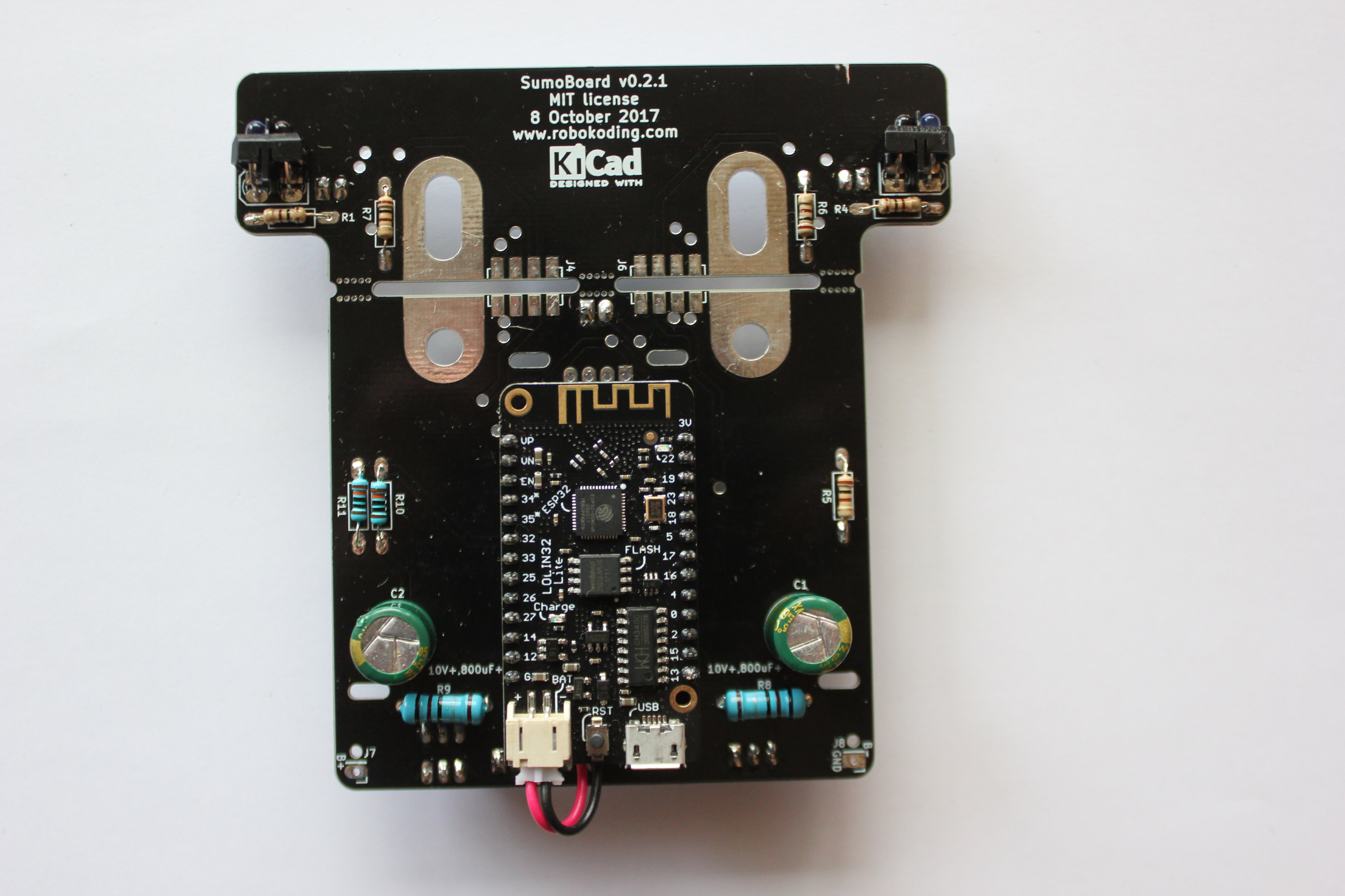
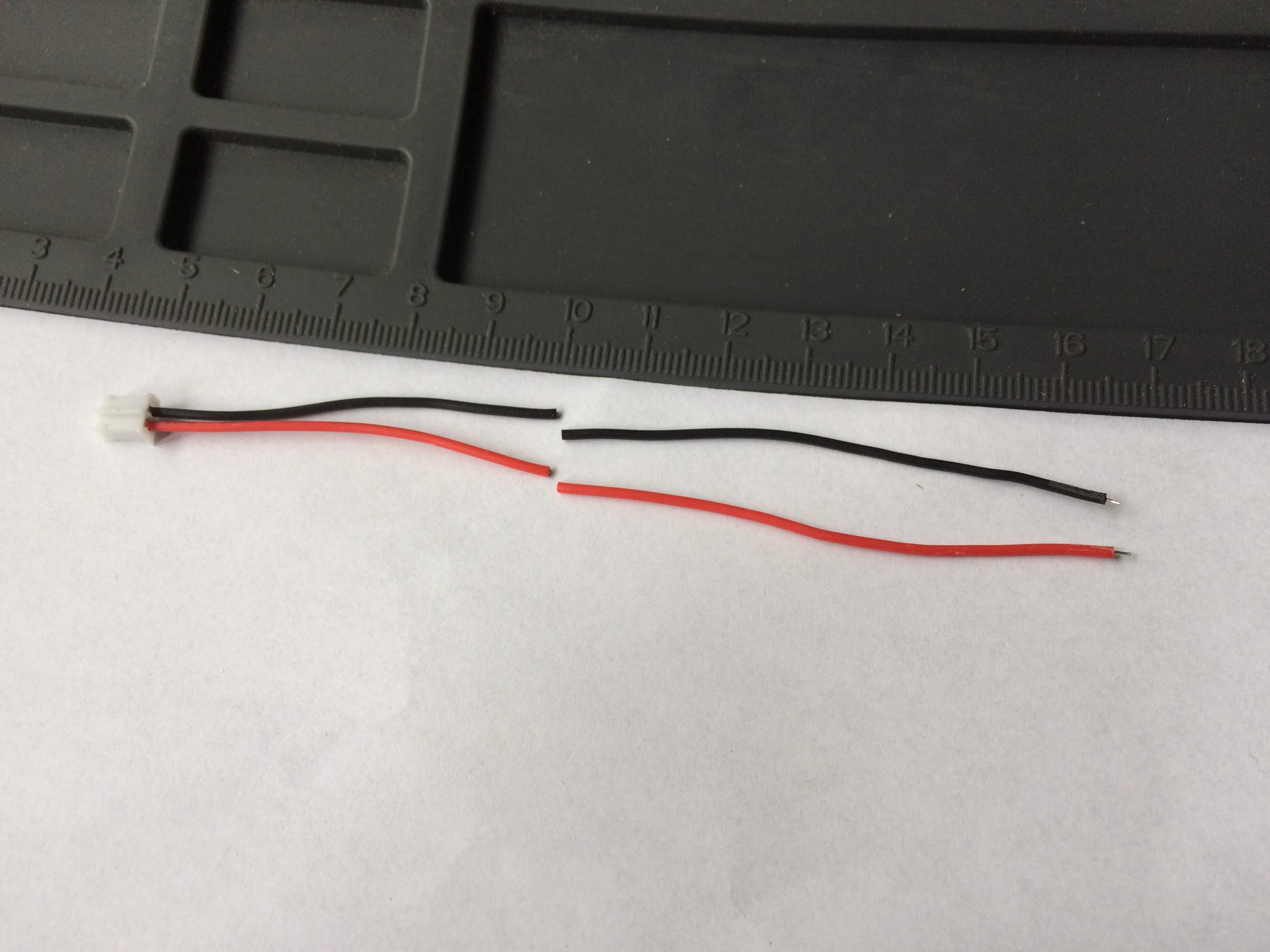
8. Solder the microcontroller power cable
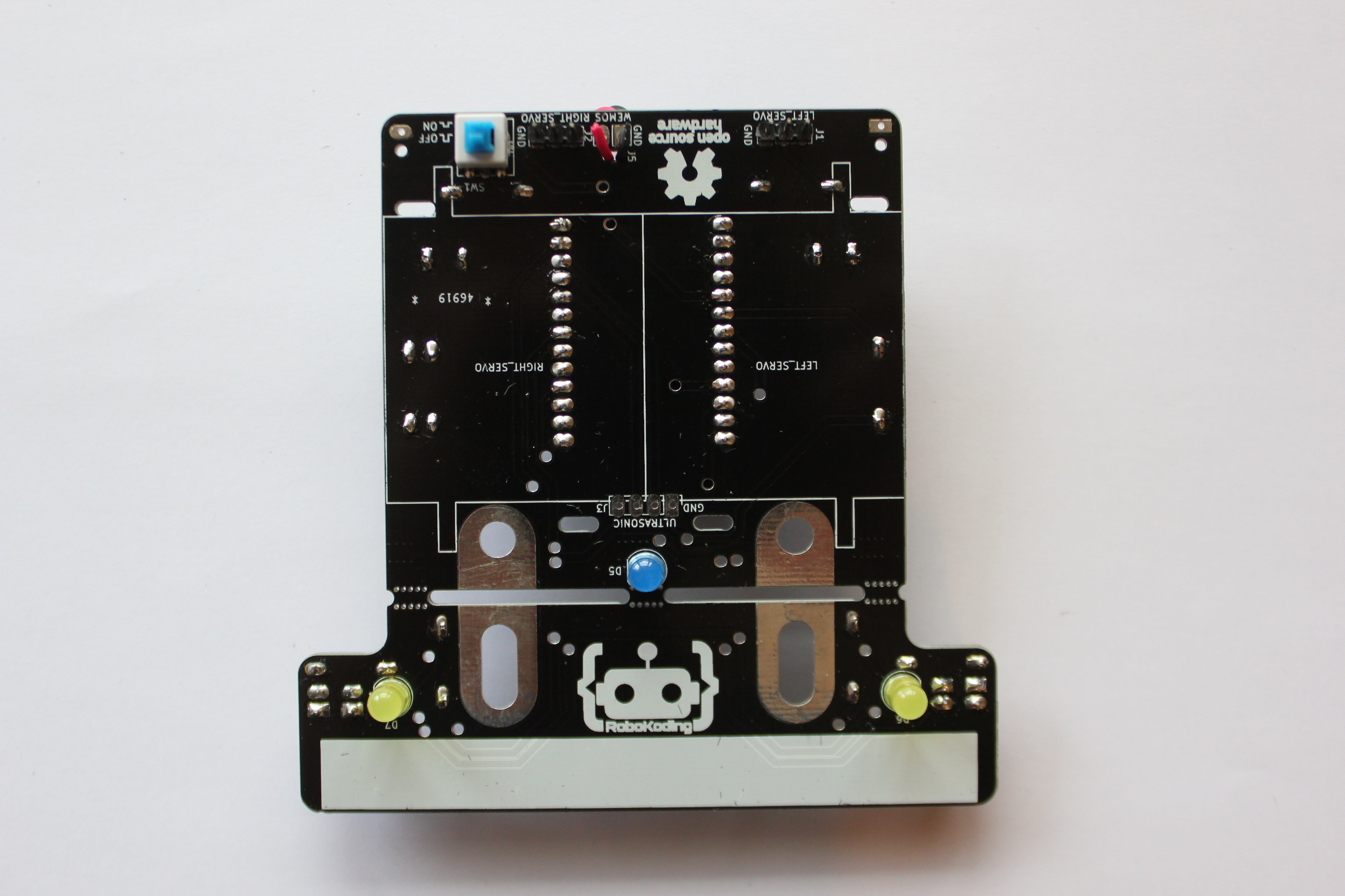
Connect the power cable to the microcontroller and put the wires trough the hole under the microcontroller trough the SumoBoard small hole. Then bend them 180 degrees to go into the holes labeled WEMOS J5 and solder them into place.
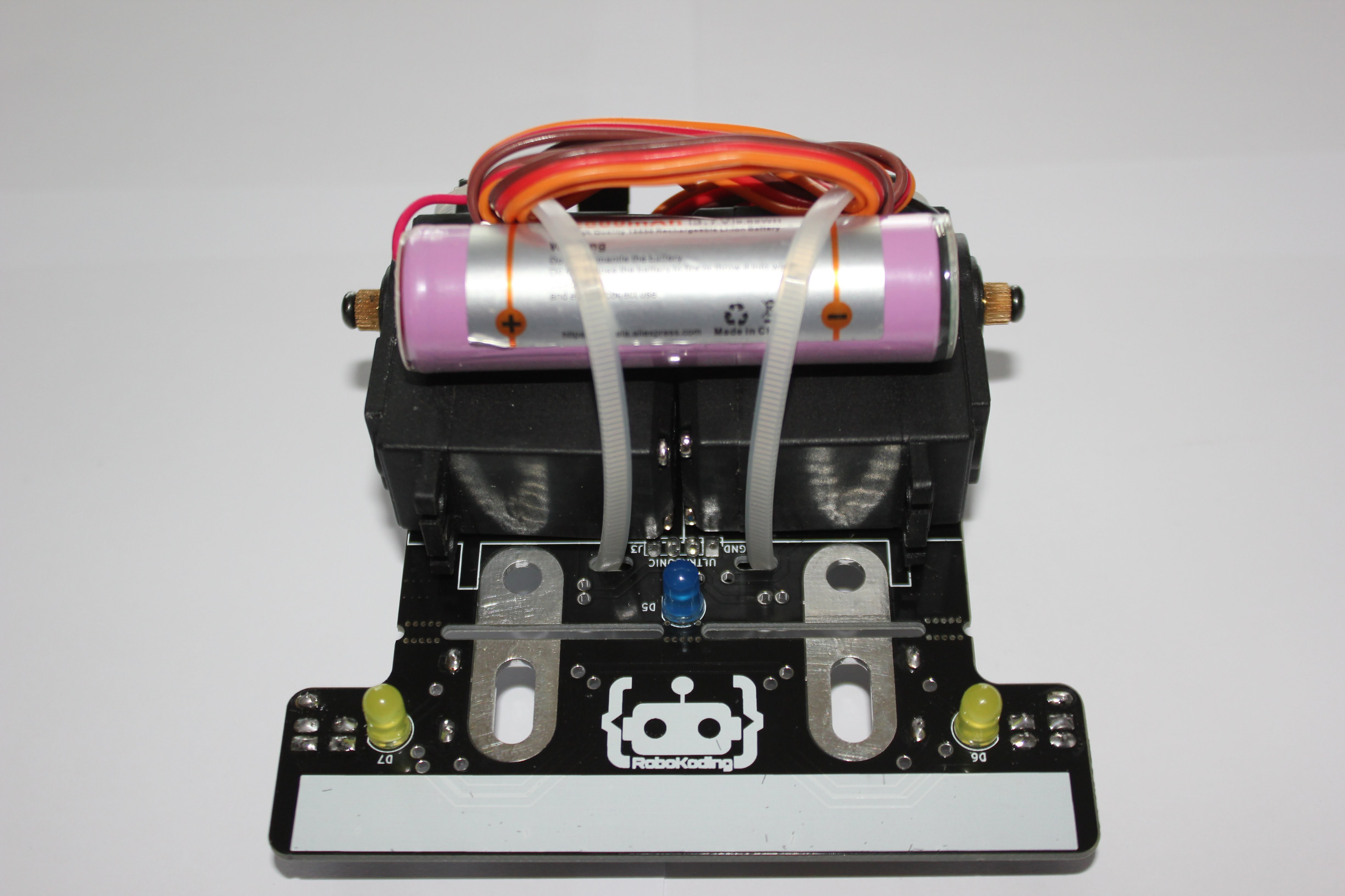
9. Place the Servomotors and the battery
First cut the power cable into half. Leave around 5.5cm on the connector side and 6.5cm on the other side. See the image below.
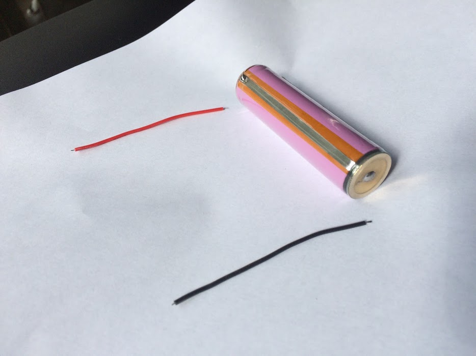
Then trim of the isolation from the cable ends and add some solder to them. Next prepare the battery, add some solder to the negative pad and to the positive. You have to peal of the isolation on the positive pad, the transparent one. Then solder the black wire to the golden negative plate and the positive to the silver looking positive strip. Keep in mind that heating the battery too much is not good, so it’s best to solder the wires quickly. See the image below.
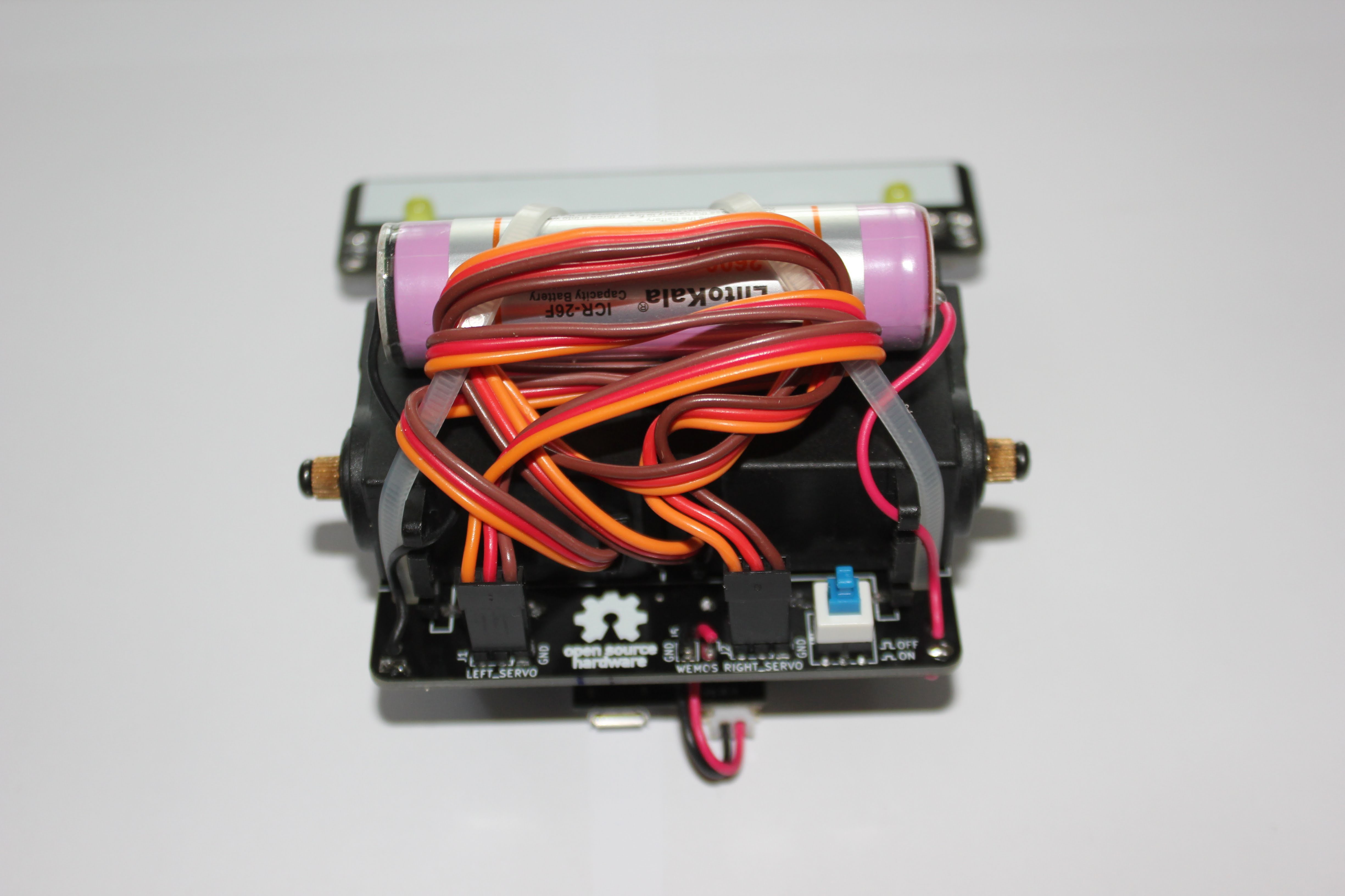
Then try to put the zip ties into the holes, above and below the LEFT_SERVO and RIGHT_SERVO rectangular markings. The zip ties are supposed to go diagonally across the Servomotors. Put the zip ties loosely just enough to lock them in place. The zip tie should go a little under the capacitors under the robot if possible.
After that place the Servomotors on SumoBoard on top of the labels LEFT_SERVO and RIGHT_SERVO. The gear that sticks out from the motor goes towards outside of the SumoBoard. The Servomotors cables should go towards the back of the robot, where the open source hardware logo is. Once the Servomotors are in place, put the battery on top of them so that the red wire is closer to the push button and then pull tight the zip ties and cut them.
Wrap the Servomotor cable around the zip ties so it doesn’t float around. Plug in the Servomotor cables according to the LEFT_SERVO and RIGHT_SERVO pin header connectors, the brown cable facing right if looking from the read of the robot. Brown cable facing the GND label on the SumoBoard.
Finally place the red and black wire from the battery from top trough the SumoBoard holes to connect them to J7 and J8. Bend the cables into the holes and solder them.
TIP: Be careful that the power button SW1, which was soldered earlier, is turned OFF. The push buttons blue push part (the part that is moving) should extend out more in the OFF position than in the ON position as drawn on the SumoBoard.
10. Solder the plow
Break off the plow part of the SumoBoard and clean the mouse bites with pliers. Then find the brackets and unscrew the bolts from them. Place the brackets under the SumoRobot to connect the plow and the 2 parts of the SumoBoard.
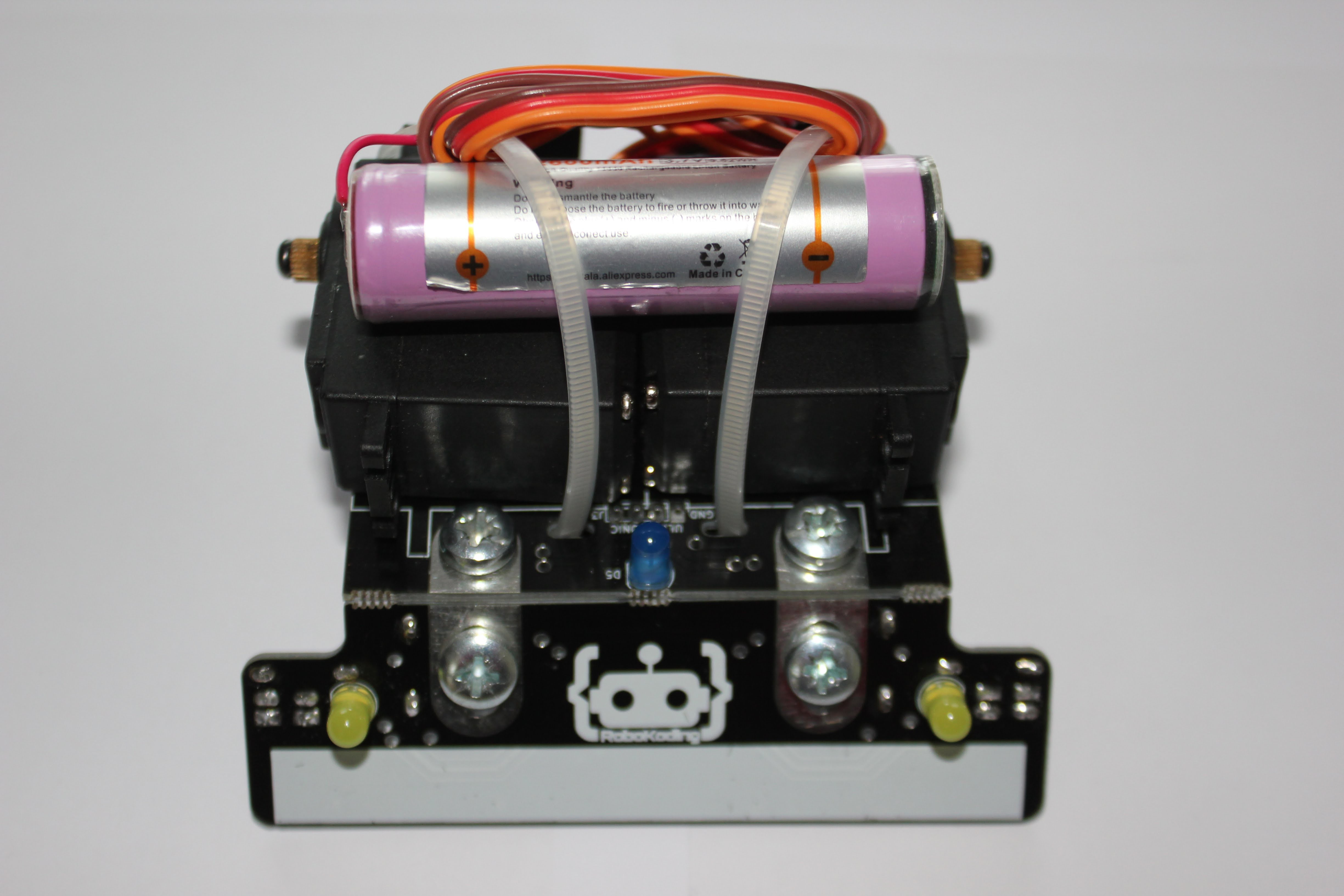
Put in the bolts and screw them together with the nuts tight so that the pads underneath the SumoRobot stay aligned and as close to each other as possible. Then solder the connection points under the SumoRobot. Make sure the soldered connection points don’t touch the metal brackets.
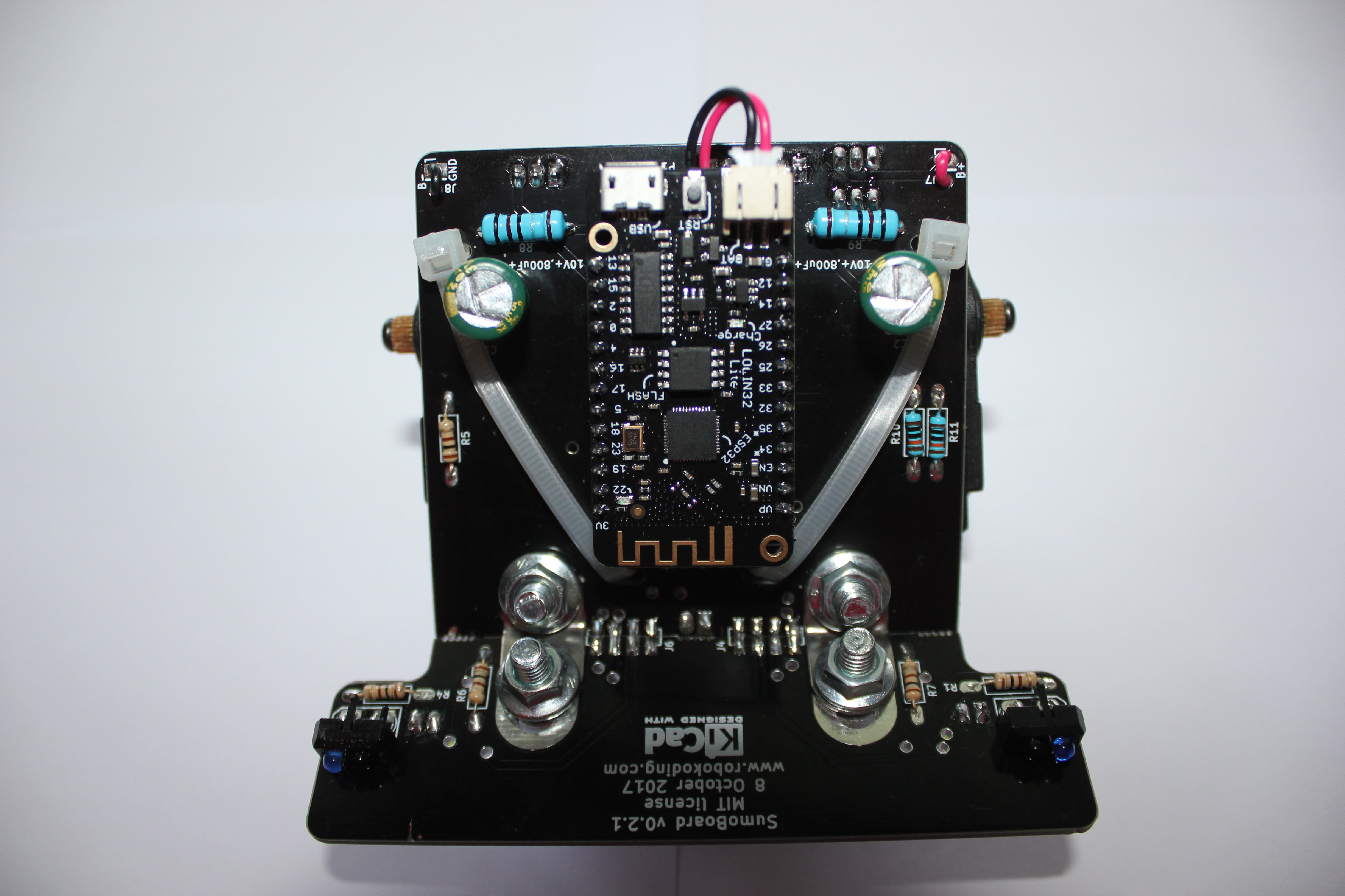
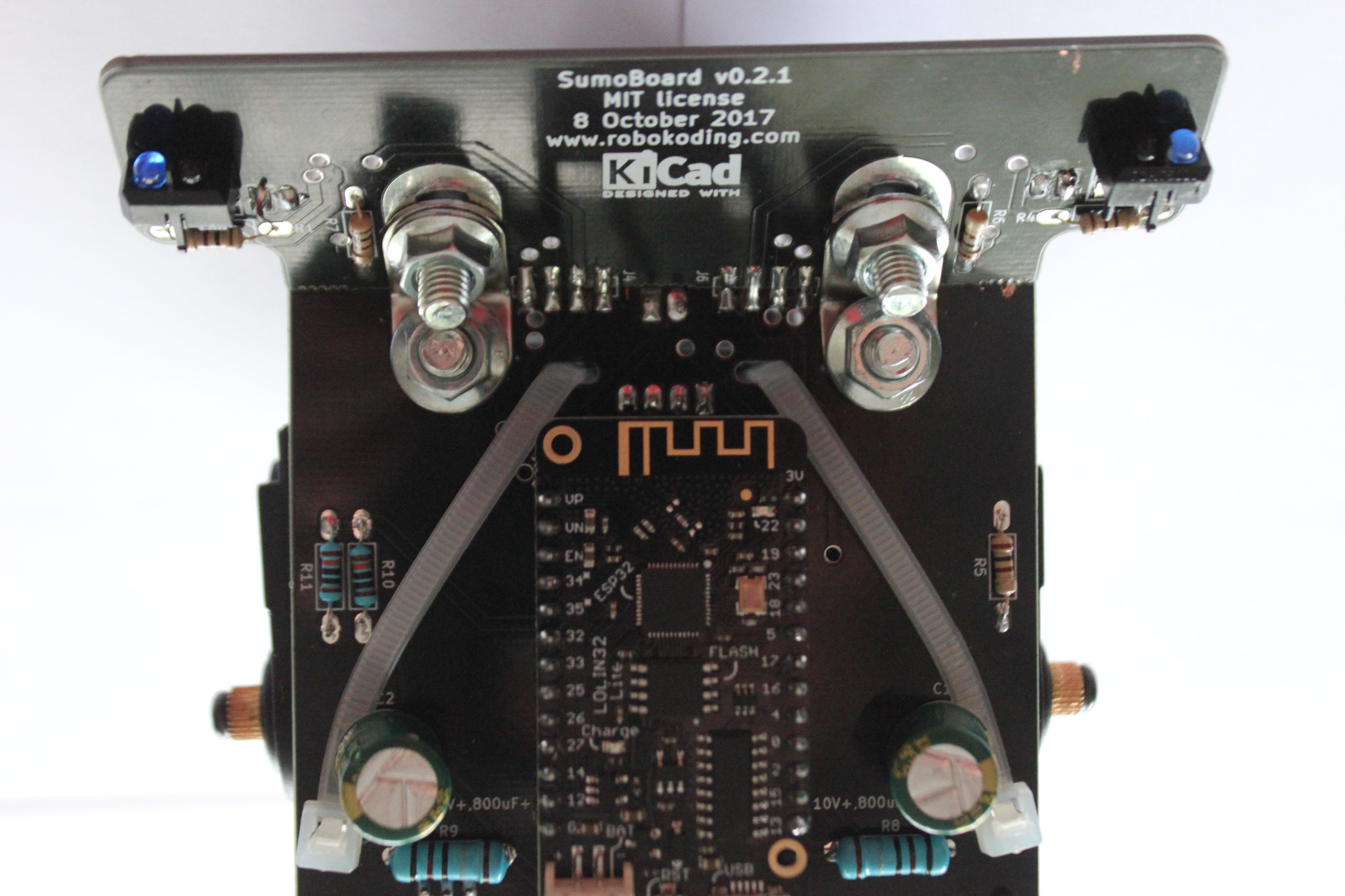
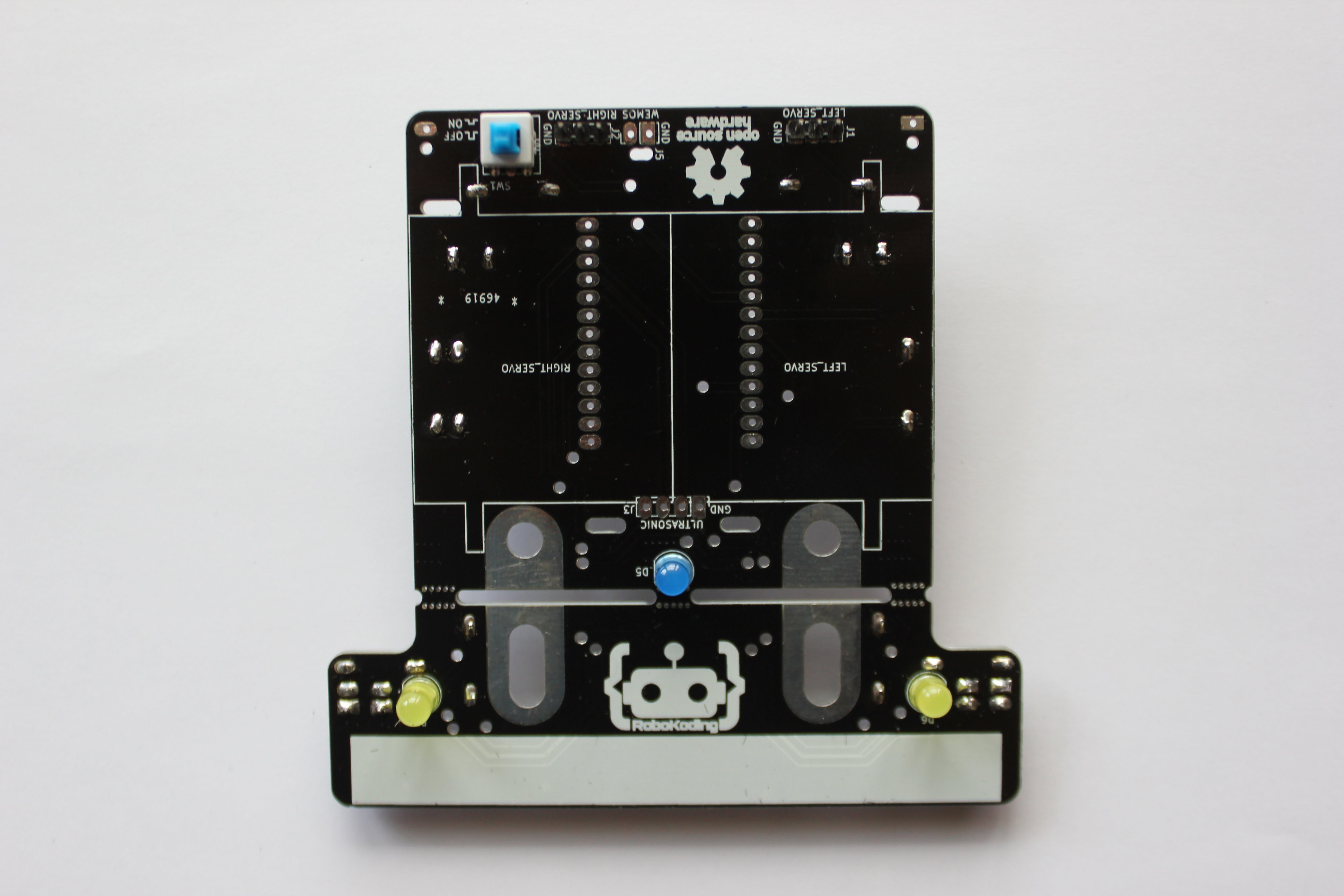
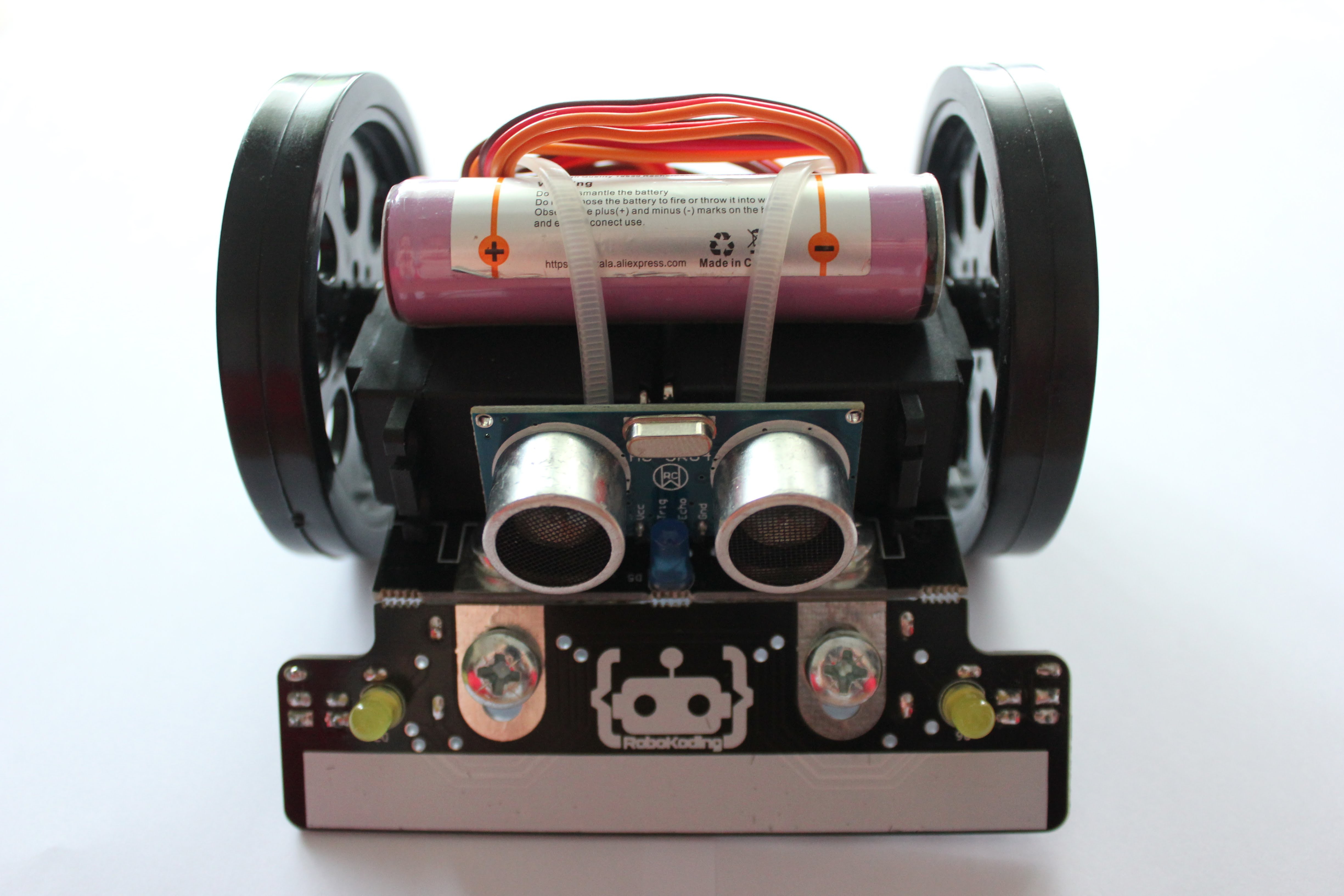
11. Solder the ultrasonic sensor
Remove the microcontroller from the bottom of the robot and place the ultrasonic sensor in the holes labeled J3. Push in the ultrasonic sensor until it touches the heads of the bolts and solder it into place. Finally find the black screws in the bags where the motors were. Place the wheels and screw the black screws to fixate the wheels.
Usage instructions
To turn ON the SumoRobot press the blue push button down. To turn the SumoRobot OFF, push the button again. In the ON state the blue push part of the button extends less from the button than in the OFF state as marked on the SumoBoard.
Connecting to WiFi is possible using the SumoManager app. The blue LED under the SumoRobot will blink when it’s trying to connect to the WiFi network. Once connected to WiFi the blue LED will be steady ON.
The yellow LED lights indicate if the SumoRobot is seeing a line. This works only on the SumoField or on a white paper with a thick black line. There are two line sensors under the plow of the SumoRobot, on the left and right. You can print your own SumoField on a A0 paper at a local print shop, download it here.
The blue LED light indicates if the SumoRobot sees something in front of it. It sees about 40cm in distance.
For charging the SumoRobot it has to be turned ON. Once you plug the micro USB into the SumoRobot’s microcontroller, it will light up the red charging LED and the microcontroller will go to sleep (turn OFF the blue and yellow LED lights). In case the microcontroller does not go to sleep properly, try plugging in the micro USB again. Once the battery is full the red LED light will turn OFF.
Debugging problems
In case you are facing some problems with the SumoRobot you can contact letstalk@robokoding.com In case you are interested to debug problems yourself you can head over to GitHub to find all the design files and software.